


Tile placement
You must understand tile placement to ensure that the array is positioned properly and to allow sufficient room for service and cable
management.
When placing the array, consider the following:
•
Typical floor tiles are 24 in. (61 cm) by 24 in. (61 cm).
•
Typical cutouts are:
○
8 in. (20.3 cm) by 6 in. (15.2 cm) maximum.
○
9 in. (22.9 cm) from the front and rear of the floor tile.
○
Centered on the tiles, 9 in (22.9 cm) from the front and rear and 8 in (20.3) from sides.
•
Service area of 42 in (106 cm) for the front and 30 in (76 cm) for the rear on the system bays.
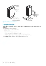
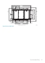
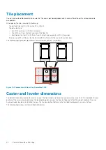
The following figure provides tile placement information for all arrays (with doors).
Rear
A
A
System
bay
System
bay
Front
F
l
o
o
r
T
i
l
e
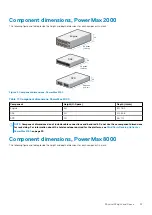
Figure 10. Placement with floor tiles, PowerMax 8000
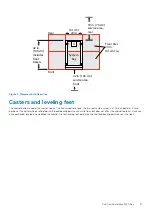
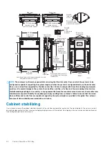
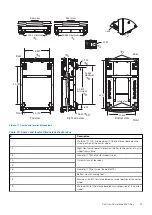
Caster and leveler dimensions
The bottom of each bay includes four caster wheels. The front wheels are fixed; the two rear casters swivel in a 1.75-in. diameter. Swivel
position of the caster wheels determines the load-bearing points on your site floor, but does not affect the cabinet footprint. Once you
have positioned, leveled, and stabilized the bays, the four leveling feet determine the final load-bearing points on your site floor.
The following figure shows caster and leveler dimensions.
32
Position PowerMax 8000 Bay


