NOTE:
Power consumption and heat dissipation details vary based on the system configuration, I/O activity, and
ambient temperatures. Ensure that the installation site meets these worst case requirements. The numbers in
Power consumption and heat dissipation
on page 14 are for fully stacked bays for a single system.
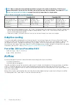
Table 6. Power consumption and heat dissipation
PowerMax 2000
PowerMax 8000
Maximum power and
heat dissipation at <26°C
and >35°C
Maximum total power
consumption <26°C /
>35°C (kVA)
Maximum heat
dissipation <26°C /
>35°C (Btu/Hr)
Maximum total power
consumption <26°C /
>35°C (kVA)
Maximum heat
dissipation <26°C /
>35°C (Btu/Hr)
System bay 1
4.4 / 6.2
14,716 / 21,038
8.4 / 11.8
28,453 / 39,903
System bay 2
N/A
8.0 / 11.4
27,214 / 38,665
a.
Power values and heat dissipations shown at >35°C reflect the higher power levels associated with both the battery recharge cycle,
and the initiation of high ambient temperature adaptive cooling algorithms. Values at <26°C are reflective of more steady state
maximum values during normal operation.
b.
Values do not include a 100W power draw for the service tray line cord attached to a customer service laptop.
Adaptive cooling
The systems apply adaptive cooling based on customer environments to save energy. Engines and DAEs access thermal data through
components located within their enclosures. Based on ambient temperature and internal activity, they set the cooling fan speeds. As the
inlet temperatures increase, the adaptive cooling increases the fan speeds, with the resulting platform power increasing up to the
maximum values shown below. These values, along with the SPS recharge power consumption, contribute to the maximum system power
consumption values over 35°C shown in
Table 6. Power consumption and heat dissipation
PowerMax 2000 and PowerMax 8000
•
DAE24 (24 Drives) = 206 VA - 702 BTU/hr
•
Engine = 255VA - 870 BTU/hr
Airflow
Systems are designed for typical hot aisle/cold aisle data center cooling environments and installation:
•
On raised or nonraised floors.
•
In hot aisle/cold aisle arrangements.
The airflow provides less mixing of hot and cold air, which can result in a higher return temperature to the computer room air conditioner
(CRAC). This promotes better heat transfer outside the building and achieves higher energy efficiency and lower Power Usage
Effectiveness (PUE). Additional efficiency can be achieved by sequestering the exhaust air completely and connecting ducts directly to a
CRAC unit or to the outside.
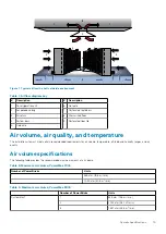
Best practice is to place a perforated floor tile in front of each bay to allow adequate cooling air supply when installing on a raised floor.
The following figure shows typical airflow in a hot aisle/ cold aisle environment.
14
System Specifications


