Page 8
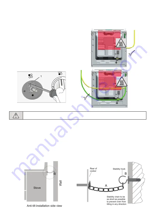
Reduced gas flow rate setting for taps
1. Ignite the burner that is to be adjusted and
turn the knob to the reduced position.
2. Remove the knob from the gas tap.
3. Use an appropriately sized screwdriver to
adjust the flow rate adjustment screw. For
LPG (Butane - Propane) turn the screw
clockwise. For natural gas, you should turn
the screw
counter-clockwise
once. The
normal length of a straight flame in the
reduced position should be 6-7 mm
4. If the flame is higher than the desired position,
turn the screw clockwise. If it is smaller turn
anticlockwise.
5. For the last control, bring the burner to both
the high-flame and reduced positions and
check whether the flame is on or off.
Depending on the type of gas tap used in your
appliance the adjustment screw position
may
Routing of the gas hose
Before connecting the gas hose, make sure that
the gas hose outlet behind the product is in the
same direction as the hose outlet
3
3
X
X
X
•
“A”
1 x Stability chain
•
“B”
1 x Stability hook with anchor sleeve
•
“A”
is factory fitted at the rear of the stove in
the centre. (See overleaf for instructions if the
removable splashback is to be fitted)
•
Position the stove and move
“A”
to touch the
wall behind the stove.
•
Mark the hole where
“A”
touches the wall
behind the stove.
•
Move the stove away from the wall to allow for
an area to work in.
All stoves can tilt if you or a child sit or lean on an open oven door. Safety regulations
stipulate that the ANTI-TILT mechanism supplied with the stove, must be fitted as shown.
•
Using a 8.0 mm concrete bit, drill a hole at
the marked position.
•
Using the Stability hook and anchor sleeve
“B”
, firmly secure
“B”
to the wall.
•
Slide the stove back in position and engage
the stability chain
“A”
onto the Stability hook
“B”
.
•
The stove is then secured and will not
accidentally tilt if downward pressure is
applied to the open oven door.
Anti-tilt mechanism


