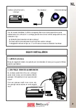
Boat
GB
24
�
�
�
�
�
�
�
�
�
�
�
�
�
�
�
�
� �
� � � �
�
�
�
�
�
�
�
�
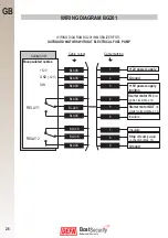
10
6
5
4
5
1
50
6
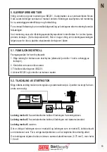
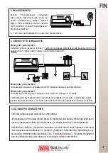
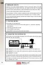
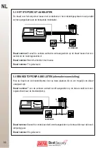
5.2 CONNECTING THE STARTER MOTOR
Cut the cable in the boat between the ignition lock and the starter solenoid at two places
as far from each other as possible.
Cable marked 4
from the central unit is connected to the cable from the ignition lock.
Cable marked 5
from the central unit is connected to the cable from the starter solenoid.
Cable marked 6
is insulated.
It is important the cable marked 4 and the cable marked 5 are connected exactly as descri-
bed above. See that the connections are made properly in order to avoid start problems.
If the cables are extended, the same cable dimension (0.75 mm
2
) must be used as a mini-
mum, preferably use 1.5 mm
2
.
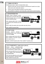
5.1. FUNCTION CONTROL
The procedure for each break point:
1. Cut the cable for the circuit to be broken (either ground or + connection, depending
on the function).
2. Check that the motor does not start.
3. Connect BG201’s relay function
4. Activate BG201 and check that the motor does not start.
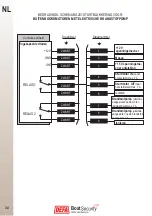
5. IMMOBILIZER CIRCUITS
Important to note when installing the BG201: There are nine black cables in the cable
loom emerging from the central unit that are only marked on their ends. This marking
should be removed during assembly to make identification and hot-wiring more difficult.
To make trouble shooting easier, mark the cables at random.
During installation, all of the connection points/break points must be measured and conti-
nuity checked to ensure correct function of the immobilizer (see 5.1. Function control).
It is very important that the assembly instructions are followed closely in order not to affect
existing functions in the boat.

