background image

Boat

GB

21

Preparing to install the BG201:

Read the installation instructions thoroughly before you begin! 
Take care when cabling, connecting cables and connecting to ground. Remember that 

moisture in the cable connectors can easily lead to corrosion. The installation should be 

checked annually in order to guarantee the function of the immobilizer.
If a fused connection is required, separate fuses must be used. Unfused circuits may 

cause fires if the cables are pinched or otherwise damaged.

Installation instructions must be followed. DEFA AS waives all liability to damages in the 

case of damage that is caused by incorrect installation.

Document your installation!

This makes future service and trouble shooting of the immo-

bilizer easier. 

TABLE OF CONTENTS

Installing the BG201  


22

Connection diagram:  


- without electrical fuel pump 

26

- with electrical fuel pump   

27

Содержание BG201

Страница 1: ...d by DEFAAS Norway Boat Distributor Finland OY KAHA AB Pl 117 FIN 01511 VANTAA FINLAND AK 02 06 8201 B www defa com Distributor Norway AS S rensen og Balchen PB 134 HOLMLIA N 1203 OSLO NORGE Distribut...

Страница 2: ...B g 2 0 1 Monteringsanvisning Asennusohje Installation Manual Montagehandleiding Boat www defa com...

Страница 3: ...r anslutning via s kring kr vs m ste en separat s dan kopplas in om ingen befintlig s kring i b ten kan anv ndas G rs inte detta finns risk f r brand i b ten vid ett s enkelt fel som att en kabel kom...

Страница 4: ...er beh ver satsen endast kompletteras med kabelskor och skruvar I vissa b tar b tmodeller kan ytterligare komplettering av materialet beh vas Till exempel Kablage kan beh va f rl ngas i vissa b tmodel...

Страница 5: ...kabel som l mnar sp nning n r t ndningen r tillslagen och d motorn krankas r denna felaktigt inkopplad fungerar inte startsp rrarna Svart ledning m rkt 2 Jordmatning till st ldskyddet Ansluts till jo...

Страница 6: ...v gag ngss tt f r varje brytpunkt 1 Klipp skyddspunkt alt jorda eller koppla beroende p funktion 2 Kontrollera funktion genom startf rs k skall ej starta 3 Anslut rel funktionen i BG201 4 Aktivera BG2...

Страница 7: ...rt ledning m rkt 9 ansluts jord Isolera svart ledning m rkt 7 5 4 BR NSLEPUMP Alternativ inkoppling Kapa motorns befintliga ledning till br nslepumpen p 2 punkter s l ngt ifr n varandra som m jligt Sv...

Страница 8: ...enoid Max 7A Jord Kabelf rg 15 matning 1 Stoppkrets Paral lellkopplas Max 7A Jord 12V matning St ldskyddsenhet Ingjutna kablar Isoleras Isoleras 12V GND 12V IGN UTOMBORDARE UTAN ELEKTRISK BENSINPUMP R...

Страница 9: ...ing 7 Bensinpump nden mot bensinpump Max 7A Isoleras 12V matning St ldskyddsenhet Ingjutna kablar Isoleras Bensinpump nden mot styrbox Max 7A 12V GND IGN REL 1 REL 2 UTOMBORDARE MED ELEKTRISK BENSINPU...

Страница 10: ...tilkobling med sikring kreves m egen separat sikring anvendes Usikrede kretser kan for rsake brann om ledningene kommer i klem eller skades p annen m te Monteringen m utf res i henhold til monterings...

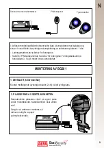
Страница 11: ...for forlengelse Forlengelseskabel p henholdsvis 3 5 og 8 meter finnes som tilbeh r Sentralenhet med radiomottaker Fjernkontroller PIN kodepanel MONTERING AV BG201 9 2 PLASSERING AV SENTRALENHETEN Sen...

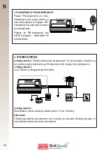
Страница 12: ...s direkte p b tens batteri 12 via 1A sikring Alternativt Tilkobles plussledning p startmotor via 1A sikring om alternativ tilkobling benyttes vil ikke lysdioden blinke ved avsl tt hovedstr m 10 3 PLAS...

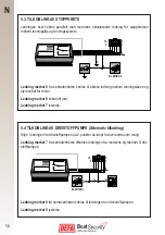
Страница 13: ...rytepunkt 1 Klipp ledning for kretsen som skal brytes alternativt jord eller koble avhengig av funksjon 2 Kontroller at motoren ikke starter 3 Tilkoble rel funksjonen i BG201 4 Aktiver BG201 og kontro...

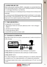
Страница 14: ...t 8 fra sentralenheten kobles til ledningen mot drivstoffpumpen Ledning merket 9 isoleres 5 3 TILKOBLING AV STOPPKRETS Ledningen skal kobles parallelt med motorens eksisterende ledning for stoppkretse...

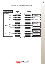
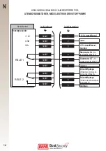
Страница 15: ...ge Ledningsmerking 15 str mtilf rsel Stoppkrets Parallell kobles Maks 7A Jord 12V str mtilf rsel Sentralenhet Innst pte kabler Isoleres Isoleres 12V GND 12V IGN KOBLINGSSKJEMA BG201 KJ RESPERRE FOR UT...

Страница 16: ...A BG201 KJ RESPERRE FOR UTENBORDSMOTORER MED ELEKTRISK DRIVSTOFFPUMPE Startmotor IN Fra tenningsl s Maks 7A Startmotor UT Til startersolenoid Maks 7A Jord 15 str mtilf rsel tenning Drivstoffpumpe Ende...

Страница 17: ...ssa saa niinkin pieni vika kuin johdon puristuksiin joutuminen tai muu vaurioituminen aikaan venepalon vaaran Tee asennusty t huolellisesti Viallinen tuote tulee kuluttajansuojalains d nn n mukaan kor...

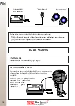
Страница 18: ...assa jotta kauko ohjai melle saadaan mah dollisimman pitk kantomatka Keskusyksikk radiovastaanotin PIN koodipaneeli Sarjaa ei tarvitse normaalisti t ydent miss n asennuksissa PIN koodipaneelin kaapeli...

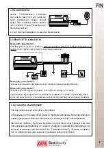
Страница 19: ...in 3 PIN KOODIPANEELI Asenna PIN koodipaneeli kojelautaan siten ett se n kyy hyvin ulos ja ett pa neelin painikkeeseen p see helposti k siksi PIN koodipaneeli voidaan asentaa my s moottoriin Yhdist PI...

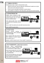
Страница 20: ...Maadoita merkill 9 varustettu johto Erist merkill 7 varustettu johto Kytke n moottorin virtalukon ja sytytysj rjestelm n v lisen pys ytyspii rin johtimen rinnalle Kytke varkaussuojalta tuleva johto m...

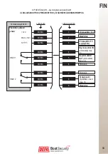
Страница 21: ...15 sytytysvirta MUSTA MUSTA 1 2 3 4 5 6 7 8 9 Pys ytyspiiri kytket n rinnan max 7 A Maadoitus Virransy tt 12 V Varkaussuojayksikk Yksikk n juotetut johdot RELE 1 RELE 2 Eristet n Eristet n MUSTA MUSTA...

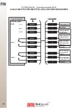
Страница 22: ...virta MUSTA MUSTA 1 2 3 4 5 6 7 8 9 Bensiinipumppu pumpulle max 7 A Eristet n Virransy tt 12 V Varkaussuojayksikk Yksikk n juotetut johdot RELE 1 RELE 2 Eristet n Bensiinipumppu virransy tt n max 7 A...

Страница 23: ...the immobilizer If a fused connection is required separate fuses must be used Unfused circuits may cause fires if the cables are pinched or otherwise damaged Installation instructions must be followe...

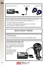
Страница 24: ...it with radio receiver Remote controls PIN code panel For most installations the installation kit will only need additional cable shoes and screws In some cases the kit may require additional componen...

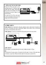
Страница 25: ...onnected directly to the boat s battery through a 1A fuse OR Is connected to the plus cable on the starter motor through a 1A fuse If this alternative connection is used the LED will not flash when th...

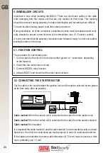
Страница 26: ...The procedure for each break point 1 Cut the cable for the circuit to be broken either ground or connection depending on the function 2 Check that the motor does not start 3 Connect BG201 s relay func...

Страница 27: ...fuel pump Cable marked 8 from the central unit is connected to the cable going to the fuel pump Cable marked 9 is insulated 5 3 CONNECTING THE STOP CIRCUIT The cable must be connected in parallel wit...

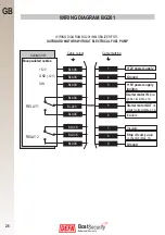
Страница 28: ...Cable marking 15V power supply ignition Stop circuit parallel connection Max 7A Ground 12V power supply Central unit Encapsulated cables Insulate Insulate 12V GND 12V IGN WIRING DIAGRAM BG201 IMMOBILI...

Страница 29: ...BG201 IMMOBILIZER FOR OUTBOARD MOTORS WITH ELECTRICAL FUEL PUMP Start motor IN from the ignition lock Max 7A Starter motor OUT to starter solenoid Max 7A Ground 15V power supply ignition Fuel pump En...

Страница 30: ...erde verbinding is vereist gebruik dan afzonderlijke zekeringen Niet gezekerde circuits kunnen brand veroorzaken als de draden worden ingeklemd of op een andere manier worden beschadigd De installatie...

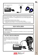
Страница 31: ...pincodepaneel moet misschien worden verlengd Verlengkabels met een lengte van 3 5 en 8 meter als reserve onderdelen leverbaar BG201 INSTALLEREN 2 CENTRALE EENHEID AANBRENGEN De centrale eenheid wordt...

Страница 32: ...n 1 A zekering aangesloten op de accu van de boot OF Wordt via een 1 A zekering aangesloten op de pluskabel op de startmotor Als deze alterna tieve aansluiting wordt toegepast knippert de LED niet als...

Страница 33: ...oet worden onderbroken ofwel de massa of de aansluiting afhankelijk van de functie 2 Controleer of de motor niet aanslaat 3 Sluit het relais van de BG201 aan 4 Schakel de BG201 in controleer of de mot...

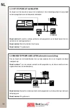
Страница 34: ...naar de brandstofpomp Draad nummer 8 vanaf de centrale eenheid wordt aangesloten op de draad die naar de brand stofpomp gaat Draad nummer 9 is ge soleerd 5 3 HET STOPCIRCUIT AANSLUITEN De draad voor...

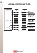
Страница 35: ...ningstoe voer ontsteking Stopcircuit parallelle aansluiting max 7 A Massa 12 V spanningstoevoer Centrale eenheid Ingekapselde draden Isoleren Isoleren 12 V MASSA 12 V ONT BEDRADINGS SCHEMA BG201 START...

Страница 36: ...OKKERING VOOR BUITENBOORDMOTOREN MET ELEKTRISCHE BRANDSTOFPOMP Startmotor IN vanaf contactslot max 7 A Startmotor UIT naar het startrelais max 7 A Massa 15 V spanningstoe voer ontsteking Brandstofpomp...

Отзывы: