Deekax TALTERI DIVK-C 60 CD Скачать руководство пользователя страница 8

8

THE CHANGES OF THE SERVICE MENU SETTINGS ALWAYS  HAVE TO BE SAVED

.

Factory setting
         10 min
           3

Factory setting
         17 

o

C

MODBUS  MENU

Check the separate Modbus manual

SEPARATE FIREPLACE SWITCH OR PRESSURE COMPENSATION

Factory setting
         10 min
           1

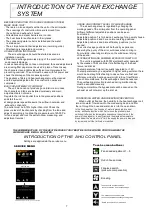
INTRODUCTION OF THE  AHU CONTROL PANEL

 0-10V external control (0-10V hood,remote monitoring) select the deployment
 SENSOR 1 "EXT"  or SENSOR 2 "EXT"

External control controls the basic speed , replaces  the fan speed set in the menu. 
Out-of-home, overpressure and boost are  in use normally.

The main screen shows the fan speed at REMOTE CONTROL and 
below of it is the speed of the supply fan.


External control fan speeds
0-2V    fan 0  
2-5V    fan 2
5-7V    fan 3
7-9V    fan 4
9-10V  fan 5

DEFAULT SETTINGS
1.  30 %
2.  40 %
3.  60 %
4.  80 %
5. 100 %

FAN SPEED PRIORITY

Fan speed preselection is performed from the control panel service  menu.
Inlet and outlet fans can be individually adjusted for five different speeds with fan speeds of 20-100%

BOOSTING FROM THE COOKER HOOD WITH CONTACT TIP INFORMATION.

Boosting time settings 0 and 5...120 min. In 0 position with different pre-data 
Boosting level settings 1...4 (the air impellers higher than basic speed), can be 
adjused also from the settings menu. 


Overpressure duration specification 0 and 5...20 min. In 0 position with different 
pre-data 
Overpressure limit regulation 1...4 (inlet air impeller higher than outlet air impeller) 


REGULATION of the INLET AIR TEMPERATURE 
Inlet air temperature  range 5...30 

o

C, 

can be adjusted   via SETTINGS menu 

CO

2

 AND/or RH SENSORS ACTIVATION 


CO

2

 AND HUMIDY PERCENTAGE SETTING  

Note: set  the sensor on  in the settings menu 

SPEED CONTROL WITH  A COOKER HOOD (0-10V)

Содержание TALTERI DIVK-C 60 CD

Страница 1: ...OME TRUE WITH THE RECOVERY SYSTEM TALTERI removes used air from interior and brings in fresh air Humidity and impurities are exhausted through thermal recovery unit that heats the filtered ambient air cost effectively The fresh warm air is channelled draught free and noise free into the premises in necessary quantities ENSURE THE QUALITY OF AIR EXCHANGE DIVK C 60 CD QUALITY TESTED ...

Страница 2: ...icture is shown right handed R unit Talteri heat recovery system 1 EXHAUST AIR 2 OUTDOOR AIR 3 EXTRACT AIR 4 SUPPLY AIR DUCT OUTLETS HANDEDNESS RIGHT 4 EXHAUST AIR 3 OUTDOOR AIR FOR 2 EXTRACT AIR 1 SUPPLY AIR 5 ELECTRIC WIRING DUCT OUTLETS HANDEDNESS LEFT l s Pa 200 100 40 60 Extract air Supply 20 Air flow External ductwork pressure 100 80 60 40 Fan speed 40 50 60 70 80 90 100 Fan power W 16 21 34...

Страница 3: ...e made at a least 10 mm in the bore copper pipe or Relatively stiff hose The water pipe Making about 10 cm in the water trap and the tube is connected to a floor drain The water line shouldnt be connected directly to the sewer WALL MOUNTING The wall mounting kit includes a ceiling mounting plate a wall mounting plate and 15mm thick insulation pieces The roof mounting plate is attached to the machi...

Страница 4: ... not tighter MOUNTING PLATE BINDING UPPER SURFACE IS INSTALLED 5 mm BELOW THE ROOF SURFACE LEAVE A 40 50MM GAP BETWEEN THE CEILING AND THE FRONT EDGE OF THE MOUNTING PLATE SERVICE HATCH M8 THREADED BAR BACKUP NUT THE UNIT IS PULLED INTO THE MOUNTING PLATE RAILS MEASURES OF THE MOUNTING PLATE SERVICE HATCH THE UNIT IS ATTACHED TO THE MOUNTING PLATE FROM THE INSIDE BY FOUR M8 BOLTS 1 EXHAUST AIR 2 O...

Страница 5: ...0 10v set value 0 as contact tip information Internal connection of the HRV unit Input power cord 230V 50 Hz 10 A RJ12 2 5 m AHU To control panel Input 230V 50 Hz 10 A power cord plug Pulse switch Input power cord 2 m plug connection box cable 1 m External connections of the HRV unit are connected to the connection box located on the top the unit The unit is equipped with a power plug The unit is ...

Страница 6: ... Gr Pi R bl Wh gr Grey Yellow Green Brown White Br gr Ye br Wh ye Red Blue Pink 0 10 0 24 Input 230V 50 Hz 10 A power cord plug IU POST HEATTER PRE HEATER Coupler female 1934516 white Coupler male 1934512 white Supply air fan Extract air fan TRIAC PreH TRIAC PostH FUSE SUPPLY EXTRACT EXTRACT SUPPLY CIRCUIT BOARD ECU_M CONTROLL PANEL POST HEATER PRE HEATER ALARM HEAT EXHANGER BYPASS SUMMER WINTER T...

Страница 7: ...house Adjustable position 2 and 3 are normal working positions Adjustable position 4 and 5 are efficiency positions i e for saunas The correct usage positions will be found by experience observing the purity of the air or sultriness when coming in from outside observing moisture on the windows or drying of the sauna AFTERHEATING AND SUMMER BYPASS OF INLET AIR The unit is equipped with 500W electri...

Страница 8: ...TINGS 1 30 2 40 3 60 4 80 5 100 FAN SPEED PRIORITY Fan speed preselection is performed from the control panel service menu Inlet and outlet fans can be individually adjusted for five different speeds with fan speeds of 20 100 BOOSTING FROM THE COOKER HOOD WITH CONTACT TIP INFORMATION Boosting time settings 0 and 5 120 min In 0 position with different pre data Boosting level settings 1 4 the air im...

Страница 9: ...on are enabled changes are only if needed CHANGES OF THE SERVICE MENU SETTINGS ALWAYS HAVE TO BE SAVED 9 The summer bypass plate control The user of the unit can set the bypass plate manually to SUMMER WINTER or AUTOMATIC mode In summer mode the bypass plate is activated In the automatic mode the plate works according to outside temperature Set value 15 20 oC The automatic mode has adjustment ampl...

Страница 10: ...stening screw see the picture When removing the supply airfan move first the reset button of the overheat protection aside by removing the metal plate Unplug the fan plug connector Remove the fastening screws of the fan and pull the fan out of the machine REMOVING OF THE ELECTRICAL HOUSING The screws of the bypass damper The screws of the electrical housing The electrical housing can be removed fo...

Страница 11: ...l is defrozen by using the preheater The power of the preheater is mainly adequate to keep the heat recovery cell defrozen In extreme conditions if the power of the preheater is not sufficient the supply fan power will be reduced or stopped by the freezing protection thermostat when the exhaust air temperature drops below the set value 0 C The supply fan starts when the exhaust air temperature ris...

Отзывы: