


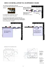


SYSTEM COMPONENTS
Picture 1
1 Air exchange unit......DIVK-C60 CD
2 Control hood.....e.g. .DX-ULTRA- PG EC
3 Exhaust air outlets..
4 Channel noise deductor...... Ø 125
5 Exhaust air for the system....... Ø 125
6 Outdoor air for the system...... Ø 125
7 Interior air supplies............ Ø 125
pictured right handed (R)
Picture 1
****
utility room
washroom
clothing
room
bed room living
room
OUTDOOR AIR
EXTRACT AIR
kitchen
SUPPLY AIR
1
2
3
5
6
7
4
DIVK
EQUIPMENT DETAILS AND TECHNICAL DATA
1 Exhaust air out.............. 125 mm
2 Outdoor air for the system ..... 125 mm
3 Exhaust air for the system...... 125 mm
4 Interior air supply........ 125 mm
6 Door switch
7 Supply fan, adjustable.. 118W
8 Exhaust fan, adjustable.... .118W
9 Heat exchanger
10 Afterheater,adjustable, 500w
11
Preheater, adjustable, 500w
12 Extract air filter (G4) ISO Coarse>75%
13 Suply air filter (F7) ISO ePM1
14 Exhaust of condensing water
16 Manual overheat protection of the preheater
17 Manual overheat protection of the afterheater
18 Summer bypass appliance
2
In the picture is shown right handed (R) unit
Talteri heat recovery system
1 EXHAUST AIR
2 OUTDOOR AIR
3 EXTRACT AIR
4 SUPPLY AIR
DUCT OUTLETS
HANDEDNESS RIGHT
4 EXHAUST AIR
3 OUTDOOR AIR FOR
2 EXTRACT AIR
1 SUPPLY AIR
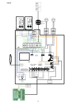
5 ELECTRIC WIRING
DUCT OUTLETS
HANDEDNESS LEFT
l/s
Pa
200
100
40
60
Extract air
Supply
20
Air flow
E
xt
er
na
l d
uc
tw
or
k
pr
e
ss
u
re
100%
80 %
60 %
40 %
Fan speed %
40
50
60
70
80
90
100
Fan power W
16
21
34
52
77
116
152
Sound pressure level L
pA
in the room 10m2 absortion dB(A)
20
24
28
33
36
40
43
Hz
E S
E S
E S
E S
E S
E S
E S
63
35 46
42 53
47 57
51 59
55 65
57 67
59 68
125
32 42
37 49
43 53
47 56
50 61
53 64
56 66
250
35 39
41 47
46 52
51 57
54 61
57 64
60 67
500
22 42
31 47
32 54
35 60
39 65
43 68
46 71
1000
28 40
34 47
39 52
41 58
44 62
46 64
49 66
2000
6 35
14 43
20 51
24 58
28 62
31 65
33 68
4000
* 25
5 36
12 45
17 52
22 57
25 61
29 65
8000
* 10
* 23
4 35
9 45
14 52
18 56
21 60
Total power level L
wa
29 42
35 49
40 56
43 63
46 67
49 70
51 73
weighted
sound
pressure
levels for
exhaust(E)
and supply(S)
channels at
different
octave levels
EXHAUST AIR
OVEN
DIMENSIONS: height 645 mm, widht 598 mm,
depth 335 mm, weight 52 Kg
7
8
9
6
10
17
11
12
13
14
16
18


