decrane aerospace LCDP-9084-301-x Скачать руководство пользователя страница 7

DeCrane Aerospace Audio International, Inc.


LCDP-9084-301-x Installation Manual  


Document # 540344, Rev A1, 02/2009  


Page 6 of 16 


   Installation 


3.1    Prior to installation, the following items should be considered: 


3.1.1  During  the  design  and  layout  of  the  aircraft  cabin,  careful 

consideration of the location of this module is necessary. Some of 

the items to be considered include: 

  Space 

  Available power supply 

  Environmental conditions (temperature, humidity, etc.) 

  Length of cable runs 


3.1.2   The  LCDP-9084-301-x  shall  be  installed  to  conform  to  the 

standards  designated  by  the  customer,  installing  agency,  and 

existing conditions as to the unit location and type of installation.  


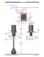
3.1.3  Mounting is accomplished by insertion of the 9G Plug-In Arm into 

BSE-9101-101-x  Plug-in  Monitor  Base.  Refer  to  Section  8.0, 

Reference  Drawings,  for  mounting  hole  diameters  and 

configuration. (This product has the ability to meet or exceed all of 

the industry’s expectations and there is no need for it to be stowed 

during take-off or landing.) 


3.1.4  Locate the monitor as close to the source equipment as possible in 

order  to  reduce  the  possibility  of  noise  introduced  into  the  video. 

Refer to Section 7.0 for unit dimensions. 


 3.2  Unpacking and Inspection 


3.2.1  Carefully  open  the  packaging  and  remove  the  LCDP-9084-301-x. 

Verify that all components have been included in the package per 

the  packing  list.  Inspect  the  unit  for  damage.  Retain  the  packing 

materials and packing list.  


3.2.2  If  damage  has  occurred  during  shipping,  a  claim  should  be  filed 

with DeCrane Aerospace Audio International WITHIN 24 hours and 

Return Request Authorization Number 

shall be obtained from 

DAAI  by  contacting  the  Repair  Department  at  501.801.8101. 

Repackage the unit in its original packaging materials and return it 

to  DAAI  following  instructions  given  by  the  DAAI  representative. 

Refer to the front cover of this manual for address. If no return is 

necessary,  retain  the  packing  list  and  the  packing  materials  for 

storage. 


Содержание LCDP-9084-301-x

Страница 1: ... Industry Drive North Little Rock AR 72117 Phone 501 955 2929 Fax 501 955 2988 www decraneaerospace com Installation Operation Manual LCDP 9084 301 x 8 4 LCD Monitor with the 9G Plug in Arm Document 540344 ...

Страница 2: ...tion 8 0 A1 02 2009 Added 9G Plug In Arm and no stow option throughout Moved BSE 9101 10x x to Purpose of Equipment Section 1 2 from Optional Equipment Section 1 3 the base is not optional Removed common circuit ground and chassis ground connections Section 3 4 2 Added Composite video connections Section 3 43 Reference Documents or latest revision Document Description 525748 B2 LCDP 9084 301 1 Out...

Страница 3: ...ility 5 3 0 Installation 6 3 1 Prior to Installation 6 3 2 Unpacking and Inspection 6 3 3 Cautions Warnings 7 3 4 Wiring Requirements 7 3 5 Electrical Characteristics 8 3 6 Mating Connector Information 9 3 7 Pinout Assignment Descriptions 9 4 0 Operation 10 4 1 Controls 10 4 2 Control Functions 10 5 0 Instructions for Continued Airworthiness 11 6 0 Troubleshooting 11 6 1 Cleaning Method 11 6 2 Gen...

Страница 4: ... the model number the monitor possesses Composite NTSC PAL SECAM video or Serial Digital Interface video Both models display 800 x 600 SVGA resolution A state of the art thin film transistor active matrix drive system provides brilliant and accurate color reproduction excellent high contrast images cross talk suppression and fast response time with no distortion or smearing The BSE 9101 10x x Plug...

Страница 5: ...ls are provided via an on screen menu These controls include picture size position controls as well as contrast brightness and color hue for video 2 2 Typical Application 2 3 Typical Interfaces The 1 unit has level compliant sources of composite video This unit is capable of interfacing with and accepting input from all analog video capable source equipment from DeCrane Aerospace Audio Internation...

Страница 6: ...e Release Button halfway through the button s travel releases the pivot lock and allows the horizontal support to move from either 0 or 180 stations Further depression of the Release Button allows removal of the arm from the base Motion range allowances shown below Release Button TOP VIEW SIDE VIEW 3 0 Note This product has the ability to meet or exceed all of the industry s expectations and there...

Страница 7: ...ity to meet or exceed all of the industry s expectations and there is no need for it to be stowed during take off or landing 3 1 4 Locate the monitor as close to the source equipment as possible in order to reduce the possibility of noise introduced into the video Refer to Section 7 0 for unit dimensions 3 2 Unpacking and Inspection 3 2 1 Carefully open the packaging and remove the LCDP 9084 301 x...

Страница 8: ...tic Discharge guidelines shall be followed 3 4 Wiring Requirements 3 4 1 Introduction The installing agency shall supply and fabricate all external cables and mating connectors The length and routing of external cables should be carefully studied and planned before attempting installation of the equipment Allow adequate space for installation of cable and connectors Avoid sharp bends and placing c...

Страница 9: ...A 28 VDC Operating Voltage Range 18 to 32 VDC Screen Size 8 4 21 34 cm diagonal Screen Resolution H x V 800 x 600 SVGA Luminance 145 cd m Color Depth 6 bits per color 18 bits total Contrast Ratio 250 1 Typical Video Format Composite NTSC SECAM PAL or SMPTE 259M SDI Operating Temperature 5 to 131 F 15 to 55 C Storage Temperature 4 to 140 F 20 to 60 C Composite Video Input 1 V p p 75 Digital Video I...

Страница 10: ... x and 102 x models Part Number MATING CONNECTOR BSE 9101 10x 1 CBC5W1F0000 Female Plug or Equivalent Positronic Industries Size 8 Contact 110236 PIC Wire Cable BSE 9101 10x 2 DEMM5W1S Female Plug w male jackscrews or Equivalent ITT Cannon Size 8 Contact 110236 PIC Wire Cable 3 7 Pinout Assignment Descriptions 3 7 1 LCDP 9084 301 1 P1 Pin Description 1 28VDC 2 Ground 3 Video Select Switch Mom Gnd ...

Страница 11: ... navigate menu while Menu Mode is active Push and hold to turn off Menu Mode DOWN BUTTON DOWN BUTTON is used to navigate menu while Menu Mode is active DOWN BUTTON is the Video Select button when Menu Mode is not active LEFT BUTTON LEFT BUTTON is only active in Menu Mode and is used to navigate the menu and change values RIGHT BUTTON RIGHT BUTTON is only active in Menu Mode and is used to navigate...

Страница 12: ...ng 6 1 Cleaning Method The LCDP 9084 301 x should be cleaned when excessive dust or dirt becomes apparent Use a twin pack cleaning system that employs a wet pad pre moistened with an Isopropyl Alcohol based cleaner anti static solution and a lint free drying cloth DeCrane Aerospace Audio International recommends using Kleen Dry RR1205 manufactured by READ RIGHT Nanuet NY 10954 Do not use benzene a...

Страница 13: ...e 1 minute and reapply power Recheck all connections to the unit for security Check all harness runs for possible pinching Recheck all pinouts for application accuracy 6 3 Troubleshooting Chart Problem Possible Cause Solution Poor picture quality or scrambled video LCD backlight malfunction Poor video source Contact DAAI Change source Blank screen LCD not receiving power Mother board malfunctionin...

Страница 14: ...ings 8 1 LCDP 9084 301 x The following diagrams show the unit dimensions mounting locations and connector locations for the monitor All dimensions are given with tolerance of 0 03 0 08 cm Note This product has the ability to meet or exceed all of the industry s expectations and there is no need for it to be stowed during take off or landing ...

Страница 15: ... Audio International Inc LCDP 9084 301 x Installation Manual Document 540344 Rev A1 02 2009 Page 14 of 16 Note Torque fasteners allow arm movement with minimum resistance while allowing arm to remain in desired position ...

Страница 16: ...l Inc LCDP 9084 301 x Installation Manual Document 540344 Rev A1 02 2009 Page 15 of 16 8 2 BASE 9101 101 x The following diagrams show the unit dimensions for the Plug in Monitor Base Note The harness is not shown in this view for clarity ...

Страница 17: ...l Inc LCDP 9084 301 x Installation Manual Document 540344 Rev A1 02 2009 Page 16 of 16 8 3 BASE 9101 102 x The following diagrams show the unit dimensions for the Plug in Monitor Base Note The harness is not shown in this view for clarity ...

Отзывы: