decrane aerospace lcd-9084-301-x Скачать руководство пользователя страница 6

DeCrane Aerospace Audio International


LCD-9084-301-x Installation Manual  


Document # 540332, Rev A, 01/2009  


Page 5 of 18 


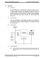
2.4.2  The  digital  video  input  accepts  SDI  Video  as  defined  by 

ANSI/SMPTE 259M-1997 digital format. 


2.4.3  SP-LCD6  is  an  external  switch  utilized  for  monitor  set-up.  The 

switch,  which  must  be  ordered  separately,  provides  configuration 

control  via  DAAI’s  proprietary  RS-485  digital  data  bus 

communication or may be configured directly to the J2 connector. 

Refer  to  Section  3.8,  Configuration  Overview,  for  monitor  set  up. 

The SP-LCD6 may be removed and stored after the monitor is set 

up or can be mounted near the monitor for frequent use. Connector 

J2 provides to the switch panel +28 VDC power and ground input, 

serial  data  bus  control,  and  unit  ID  strapping  pins  to  allow 

programming of multiple units. 


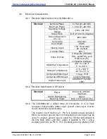
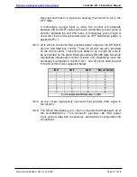
2.4.4  Device  addressing  is  accomplished  via  three  (3)  ID  pins,  which 

allow for a total of eight (8) monitors to be independently addressed 

on the data bus. 


2.4.5  The monitor casing is specially designed for EMI and noise filtering, 

guaranteeing  a  reduction  in  interference  to  ensure  a  high-quality 

display. 


2.4.6  A  shallow  mounting  depth  makes  this  monitor  ideal  for  bulkhead 

use. Convenient mounting holes are strategically located on the left 

and right sides. An optional front cover bezel (see Section 1.3) may 

be purchased for added mounting capabilities. Other plating options 

are  available  and  allow  matching  to  other  cabin  décor  of  the 

aircraft. 


3.0    Installation 


3.1    Prior to Installation 


3.1.1  During  the  design  and  layout  of  the  aircraft  cabin,  careful 

consideration of the location of this module is necessary. Some of 

the items to be considered include: 

  Space 

  Available power supply 

  Environmental conditions (temperature, humidity, etc.) 

  Length of cable runs 

3.1.2   The LCD-9084-301-x shall be installed to conform to the standards 

designated  by  the  customer,  installing  agency,  and  existing 

conditions as to the unit location and type of installation.  


3.1.3  If the adjustment switch (SP-LCD6) is to be mounted in the aircraft, 

the  following  should  be  considered;  the  pigtail  is  24  inches      

Содержание lcd-9084-301-x

Страница 1: ...7300 Industry Drive North Little Rock AR 72117 Phone 501 955 2929 Fax 501 955 2988 www decraneaerospace com Installation Manual LCD 9084 301 x 8 4 Flat Panel LCD Monitor Document 540332 ...

Страница 2: ...nnector from DAMA 15P to DEMA15PK87 Section 3 6 Troubleshooting and Continued Airworthiness are now separate sections Sections 4 0 5 0 Removed every 3 months from Section 4 1 conflicted with No periodic scheduled maintenance in Section 5 0 Added Housing info to Unit Specifications Section 6 1 Corrected SP LCD6 dimensions for cutout Section 6 2 Added center points of gravity and measurements to bac...

Страница 3: ...5 3 1 Prior to Installation 5 3 2 Unpacking and Inspection 6 3 3 Cautions Warnings 6 3 4 Wiring Requirements 7 3 5 Electrical Characteristics 9 3 6 Mating Connector Information 11 3 7 Pinout Assignment Descriptions 12 3 8 SP LCD6 Configuration Overview 13 4 0 Troubleshooting 13 4 1 Cleaning Method 13 4 2 General Troubleshooting Procedures 14 4 3 Troubleshooting Chart 15 5 0 Instructions for Contin...

Страница 4: ...nd fast response time with no distortion or smearing The monitor is designed for bulkhead mounting 1 3 Optional Equipment DeCrane Aerospace Audio International offers a comprehensive family of Cabin Control Modules and Source Equipment such as DVD players integrated touch screens speakers and other equipment that will perfectly complement the LCD 9084 301 x and will be valuable and attractive addi...

Страница 5: ...se that both Composite and VGA are applied the monitor defaults to the VGA input The user can switch between inputs or set video input priority using the On Screen Display see Section 3 8 2 2 Communication This unit incorporates an RS 485 serial data bus interface for communication purposes to other network connected devices All RS 485 serial data bus electronic interface parameters are compliant ...

Страница 6: ...sed on the data bus 2 4 5 The monitor casing is specially designed for EMI and noise filtering guaranteeing a reduction in interference to ensure a high quality display 2 4 6 A shallow mounting depth makes this monitor ideal for bulkhead use Convenient mounting holes are strategically located on the left and right sides An optional front cover bezel see Section 1 3 may be purchased for added mount...

Страница 7: ...1 model monitor 3 1 7 The maximum length of the connection to PC Graphic VGA input is 15 feet 3 2 Unpacking and Inspection 3 2 1 Carefully open the packaging and remove the LCD 9084 301 x Verify that all components have been included in the package per the packing list Inspect the unit for damage Retain the packing materials and packing list 3 2 2 If damage has occurred during shipping a claim sho...

Страница 8: ...ling agency shall supply and fabricate all external cables and mating connectors The length and routing of external cables should be carefully studied and planned before attempting installation of the equipment Allow adequate space for installation of cable and connectors Avoid sharp bends and placing cables near aircraft control cables Maintain a minimum clearance of three 3 inches from any contr...

Страница 9: ... the LCD 9084 301 x Serial digital video connections are recommended to use shielded coaxial cable in accordance with PIC V76261 or equivalent 3 4 4 RS 485 Connections RS 485 connections shall be twisted shielded cable with the shield properly grounded at the source ideal practice and floating at the load end If shield cannot be grounded at the source then ground at the load end with the source en...

Страница 10: ...50 C Storage Temperature 4 to 158 F 20 to 70 C Composite Video Input 1 V p p 75 Component RGB Input Industry Standard Digital Video Input ANSI SMPTE 259M 1997 3 5 2 Electrical Specifications SP LCD6 Electrical Power 80 mA at 28 VDC maximum Switch Backlighting Green Mounting Studs 6 32 x 0 75 inches long 3 5 3 The LCD 9084 301 x utilizes three 3 connectors J1 is a 13 pin connector that provides pow...

Страница 11: ...a bus control Three 3 ID pins are also provided on the J2 connector These ID pins allow for up to eight 8 units to be connected on the same DAAI proprietary RS 485 data bus while maintaining independent control of each unit Depending upon the necessary configuration the ID 0 ID 1 and ID 2 pins shall connect to the ID common as suggested below ID 2 ID 1 ID 0 No of Units 1 1 1 1 1 1 0 2 1 0 1 3 1 0 ...

Страница 12: ...J2 CONNECTOR PART NUMBER MATING CONNECTOR LCD 9084 301 1 RD9M10JVL0 Female Plug or equivalent Positronic Industries LCD 9084 301 2 DEMA 9P Female Plug w male jackscrews or equivalent ITT Cannon J3 CONNECTOR PART NUMBER MATING CONNECTOR LCD 9084 301 1 DD15M10JVL0 Male Plug or equivalent Positronic Industries LCD 9084 301 2 DEMA15PK87 Male Plug w male jackscrews or equivalent ITT Cannon 3 7 Pinout A...

Страница 13: ... Common J3 Pin Description 1 Red Video 2 Green Video 3 Blue Video 4 Reserved 5 Ground 6 Red Ground 7 Green Ground 8 Blue Ground 9 Key 10 Sync Ground 11 Reserved 12 Reserved 13 Horizontal Sync 14 Vertical Sync 15 Reserved 3 7 2 Wiring description for the SP LCD6 is as follows SP LCD6 Pin Description 1 28 VDC Power Input 2 Power Ground 3 Serial Data Bus A HI 4 Serial Data Bus B LO 5 Serial Data Bus ...

Страница 14: ...tor defaults out of menu mode 2 BACKLIGHT Backlighting intensity 3 FACTORY PRESET All modes may be reset to the default factory setting Select either YES or NO 4 SOURCE PRIORITY Selects priority operating mode to PC personal computer or None Setting this mode to PC allows user to normally view composite video until a PC laptop is turned on then the monitor will automatically switch to PC input upo...

Страница 15: ...g 28 VDC power is applied to the proper pins on the unit Use a voltmeter to verify correct level Remove power from the unit for at least one 1 minute and reapply power Recheck all connections to the unit for security Check all harness runs for possible pinching Recheck all pinouts for application accuracy Check data bus integrity by utilizing a voltmeter oscilloscope or other voltage instrument to...

Страница 16: ...cheduled maintenance or calibration is required for continued airworthiness of the LCD 9084 301 x If the unit fails to perform to specifications it must be removed and serviced by a qualified service facility 6 0 Specifications 6 1 Unit Specifications for LCD 9084 301 x Physical Specifications LCD 9084 301 x Screen Size 8 4 21 34 cm diagonal Housing Iridited Aluminum with black powder coat finish ...

Страница 17: ...D 9084 301 x Installation Manual Document 540332 Rev A 01 2009 Page 16 of 18 7 0 Reference Drawings 7 1 LCD 9084 301 x The following diagrams show the unit dimensions mounting locations and connector locations for the LCD 9084 301 x J2 J1 J3 ...

Страница 18: ...DeCrane Aerospace Audio International LCD 9084 301 x Installation Manual Document 540332 Rev A 01 2009 Page 17 of 18 ...

Страница 19: ...national LCD 9084 301 x Installation Manual Document 540332 Rev A 01 2009 Page 18 of 18 7 2 External Menu Switch The following diagrams show the unit dimensions and connector locations for the external menu selection switch SP LCD6 ...

Отзывы: