


DeCrane Aerospace Audio International
LCD-9084-301-x Installation Manual
Document # 540332, Rev A, 01/2009
Page 11 of 18
3.6
Mating Connector Information
All wiring harnesses to the unit shall be supplied and fabricated by the
installing agency.
J1 CONNECTOR
PART NUMBER
MATING CONNECTOR
LCD-9084-301-1
CBC13W3F140000 Female Plug or equivalent
A1 size 8 Contact: FCC4102D (Positronic Industries)
A2 size 8 Contact: 110236 (PIC Wire & Cable)
LCD-9084-301-2
DBA13W3SA19F0 Female Plug w/male jackscrews or equivalent
A1 size 8 Contact: D130344 (ITT Cannon)
A2 size 8 Contact: 110236 (PIC Wire & Cable)
J2 CONNECTOR
PART NUMBER
MATING CONNECTOR
LCD-9084-301-1
RD9M10JVL0 Female Plug or equivalent
(Positronic Industries)
LCD-9084-301-2
DEMA-9P Female Plug w/male jackscrews or equivalent
(ITT Cannon)
J3 CONNECTOR
PART NUMBER
MATING CONNECTOR
LCD-9084-301-1
DD15M10JVL0 Male Plug or equivalent
(Positronic Industries)
LCD-9084-301-2
DEMA15PK87 Male Plug w/male jackscrews or equivalent
(ITT Cannon)
3.7
Pinout Assignment Descriptions
3.7.1 Pinout assignment for the LCD-9084-301-x is as follows:
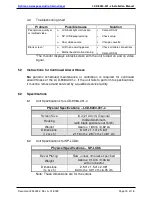
J1
Pin #
Description
1
+28VDC Power Input
2
Ground
3
Reserved
4
Monitor Status Gnd Output
5
Monitor On/Off Gnd Input
6*
SE Video Enable
7*
SE Video Common
8-10
Reserved
A1
Composite Video
A2
Serial Digital Video
A3
Reserved
* note that pins 6 and 7 tie together for single-ended composite video sources