background image

RAILMASTER-VP™ USER’S MANUAL

8


SELECT

Press 

MODE

 again, 

SEn

 displays.  Then press the

SELECT

 button to select a sensitivity level (

1

through 

5,

 one is the least sensitive and five is

the most sensitive, for tracking distant objects.)


POWER

The 

POWER

 button turns the device on and off.

If the 

SELECT

 button is pressed during power up, the

system will reset to factory default.


 1.1.3   Trigger Operation

The spring-loaded trigger controls the radar
signal transmission and speed-lock feature.  To
transmit the radar signal to begin speed
measurements, pull the trigger once.  When
released, the trigger button remains in the
pressed position.  To stop transmitting the radar
signal and receiving speed measurements, pull
and release the trigger.  This locks the speed in
the display window and flashes it every 1/2
second.  The locked speed flashes until you pull
the trigger to clear the display.


  1.1.4   Measuring a Target Speed

Aim the 

Railmaster-VP


at a moving target,

then pull the trigger.  The 

Railmaster-VP

transmits a signal, then you will see the speed of
the vehicle in the display window that is
returning the strongest signal.  To lock the
speed, pull and release the trigger.  The current
speed will blink on and off, and the system will
no longer track the target.  To clear the locked
speed, pull and release the trigger again.

Содержание RAILMASTER-VP

Страница 1: ...r Electronics Inc 715 Bright Street Decatur IL 62522 USA Canada 800 428 4315 Intl 217 428 4315 Fax 217 428 5302 www decaturradar com Rev 11 02 Copyright 2000 2001 2002 Decatur Electronics Inc RAILMASTER VP USER S MANUAL Certified ISO 9001 ...

Страница 2: ...RAILMASTER VP USER S MANUAL 2 ...

Страница 3: ...rge you to study this manual before using the railmaster VP so you can maximize the benefits of this sophisticated radar device Its digital signal processor DSP gives the device advanced capabilities unseen by many users If you are as pleased with its performance as we think you will be ask your Decatur sales representative about other Decatur products Try any one of our products and see if you do...

Страница 4: ...ery Charger 10 2 2 Controls 11 2 2 1 Mode and Select 11 2 2 2 Power 11 2 3 Display 12 2 4 Trigger Operation 12 2 5 Mounting Configurations 12 3 Operating Modes 13 3 1 Primary Menu 13 3 1 1 Backlight bL 13 3 1 2 Speed Sensitivity Level SEn 13 3 2 Secondary Menu 13 3 2 1 Speed Range Sr 14 3 2 2 Speed Units Su 14 3 2 3 Serial Output Mode Prt 14 3 2 4 Speed Hold Time ht 14 4 Serial Output Mode 15 5 Pe...

Страница 5: ... 1 Tuning Fork Test 21 7 Care Cleaning and Storage 23 8 Specifications 24 8 1 Power Consumption Parameters 24 9 Legal Requirements 25 9 1 FCC Document 25 10 Troubleshooting 26 10 1 Device Will Not Power Up 26 10 2 Radar Has Poor Range 26 10 3 Low Battery BAT 26 10 4 Error Err 26 11 Service 27 11 1 Warranty 27 11 2 Service Return Procedure 27 11 3 Maintenance and Repair Record 29 12 How to Order Ad...

Страница 6: ...wing symbols in this manual indicates a warning message about safety precautions Please read it carefully indicates a helpful tip or precaution to note 1 Quick Start If you are already familiar with radar tracking devices you will probably want to follow the quick start instructions 1 1 Initial Set Up 1 1 1 Insert the Batteries Remove the Black Decker VersaPakTM batteries from their package and ch...

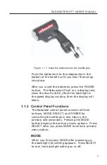
Страница 7: ...flash the backlight in the speed display window then the display will blank 1 1 2 Control Panel Functions The faceplate control panel consists of three buttons MODE SELECT and POWER for controlling the settings in two menus the primary and secondary Pressing the MODE button displays the primary menu options Press SELECT after you press MODE to select a primary menu option MODE When you first press...

Страница 8: ...er once When released the trigger button remains in the pressed position To stop transmitting the radar signal and receiving speed measurements pull and release the trigger This locks the speed in the display window and flashes it every 1 2 second The locked speed flashes until you pull the trigger to clear the display 1 1 4 Measuring a Target Speed Aim the Railmaster VP at a moving target then pu...

Страница 9: ...rovided with the batteries to store or carry them so metal objects can not contact the exposed metal end keys coins etc Remember to remove the caps before placing the batteries in the charger or the Railmaster VP If the device is idle for 30 minutes it automatically powers down to save the batteries The batteries have a minimum life of 300 charge cycles You can purchase additional batteries at har...

Страница 10: ...erate the batteries They can explode If you have problems or questions about your batteries contact Decatur Electronics 800 428 4315 Black Decker at 800 54 HOWTO 2 1 1 Removing Batteries To remove the batteries press the red button with your thumb while pulling on the battery with your fingers 2 1 2 Battery Charger Charge the batteries with only the VersaPakTM battery charger It is normal for the ...

Страница 11: ...LECT to see the setting choices for the option To access secondary menu options press and hold the SELECT button then press MODE to see each option When you see the option you want to change press the SELECT button until you see the setting for the option that you want To select the setting display it in the window until the system times out See section 3 Operating Modes for more on the menus and ...

Страница 12: ... released the trigger button remains in the pressed position To stop transmitting the radar signal and receiving speed measurements pull and release the trigger This locks the speed in the display window The display window will show the locked speed and flash it every 1 2 second The locked speed flashes until you pull the trigger to clear the display 2 5 Mounting Configurations The Railmaster VP i...

Страница 13: ...cklight bL The Railmaster VP has a backlight LCD is for use at night Press the MODE button When bL is in the display window press the SELECT button to turn the backlight on or off 3 1 2 Speed Sensitivity Level SEn When you press MODE again SEn displays While SEn is displaying press the SELECT button to choose a sensitivity level from 1 to 5 One is the least sensitive and five is the most sensitive...

Страница 14: ...speeds in mph or kph Select the speed units Su The options are 0 1 or 5 which represent 0 MPH 1 KPH 5 KNOTS 3 2 3 Serial Output Mode Prt Prt is the serial output mode option You can set the mode to the one of the following options 0 2 or 3 0 No serial output 2 Unitec Sign Protocol 3 9600 baud 8 n 1 hundreds tens ones tenths 3 2 4 Speed Hold Time ht The speed hold time ht options are 0 through 10 w...

Страница 15: ...u connect and transmit data to Decatur s large display signs in car video and PC where you can report and analyze speed data To connect to a PC plug a Decatur Electronics custom RS232 communications cable part number S769 100 into the device and the serial communications port on your PC You can purchase this cable from Decatur Electronics see section 12 How to Order Additional Products ...

Страница 16: ...ffect The radar device then determines the target vehicle s speed from the difference in frequency between the reflected and transmitted signal 5 2 Interference Sources and Remedies When properly installed and operated Doppler radar technology is extremely accurate and reliable However variations in the environment can cause situations and circumstances which can cause spurious erratic and unusual...

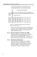
Страница 17: ...itions such as the vehicle traveling on a curve or a hill As the angle between the beam of the antenna and the target vehicle increases the displayed speed decreases Ideally an angle of 0 is preferable because the displayed speed is the actual target vehicle speed However in all uses of police radar the radar device is always at a slight angle to the target vehicle to avoid collisions Figure 5 2 1...

Страница 18: ...played speeds at different antenna to target angles Small angles less than 10 have little effect on accuracy As the angle increases the displayed speed decreases At 90 the target speed is 0 mph grossly incorrect 5 2 2 Electromagnetic Interference EMI Operating motors can produce EMI EMI from power seats or windshield wipers can also produce spurious target speeds To correct this type of interferen...

Страница 19: ...no obvious target direct the radar at a large moving object or perform one of the tests described in section 6 Field Tests to verify that the device is working properly 5 2 5 Multi Path Beam Cancellation If multi path beam cancellation occurs the target vehicle speed sporadically blinks and reappears at semi random intervals This type of interference occurs when the radar loses track of a target v...

Страница 20: ...system resumes normal operation when the RFI condition no longer exists At that time any locked speeds will display again 5 2 7 Scanning The Railmaster VP is designed to use while attached to a solid mount or hand held in a steady position Moving or scanning the antenna past stationary objects can cause the system to detect motion Obtaining a speed reading from scanning will not happen when you pr...

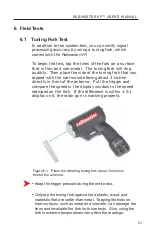
Страница 21: ...rectly in front of the antenna Pull the trigger and compare the speed in the display window to the speed stamped on the fork If the difference is within 0 1 display unit the radar gun is working properly Figure 6 1 Place the vibrating tuning fork about 3 inches in front of the antenna Keep the trigger pressed during the entire test Only tap the tuning fork against hard plastic wood and materials t...

Страница 22: ...ER VP USER S MANUAL 22 If the device does not display the expected speed contact Decatur Electronics at 800 428 4315 to arrange for service To order tuning forks see section 12 How to Order Additional Products ...

Страница 23: ... substances on the radar device When you are not using or transporting the device store it in its original packaging To clean the radar device dust it with a soft clean cloth which is free of cleaning solutions The Railmaster VP can withstand temperature variations however only the antenna is weather resistant ...

Страница 24: ... Voltage Rating 6 6 to 8 VDC All currents measured at 7 2 VDC with backlight on Standby antenna off 180 amperes Antenna ON no targets displayed 370 amperes Antenna ON 55 target displayed 440 amperes Antenna OFF segment check 888 888 180 amperes Antenna ON segment check 888 888 370 amperes ...

Страница 25: ...RAILMASTER VP USER S MANUAL 25 9 Legal Requirements 9 1 FCC Document ...

Страница 26: ...usted properly and verify that no obstructions are in front of the antenna 10 3 Low Battery BAT When the voltage is low the status indicator displays BAT so you will know when to replace or recharge the batteries 10 4 Error Err The status indicator displays Err if an internal processor error occurs Contact Decatur Electronics at 800 428 4315 for what to do when you see this error ...

Страница 27: ...6672 The full warranty on parts and workmanship does not include normal wear and tear crushing dropping fire impact immersion or damage from attempted repair or modifications by unauthorized service agents For repairs simply return the unit transportation prepaid directly to the factory or to a Decatur authorized warranty service center near you by following the instructions in section 11 2 Servic...

Страница 28: ...S for shipping the radar gun from the repair facility to the customer providing the radar gun is still under warranty The customer is charged any shipping charges above the initial 10 00 If you want to ship your package express mail or next day air you will be invoiced for the freight charges even if the gun is still under warranty If your radar is out of warranty and you would like to know the re...

Страница 29: ..._____________________________________________ ________________________________________________________ ________________________________________________________ ________________________________________________________ ________________________________________________________ ________________________________________________________ ________________________________________________________ ____________...

Страница 30: ... 3 6 volt batteries and AC 2 port charger P702 VP135 29 95 Nickel metal hydride NiMH gold label battery P702 VP110 BULK 22 25 Nickel cadmium NiCd silver label battery P702 VP100 BULK 14 95 Custom RS232 communications cable S769 100 70 00 Test Forks for testing the accuracy of your radar 77 6 and 33 2 MPH test fork set S900 11 40 00 100 6 and 45 3 KPH test fork set S900 12 40 00 Molded Holster S780...

Страница 31: ...RAILMASTER VP USER S MANUAL 31 User Notes ...

Страница 32: ...25 maintenance 27 29 maintenance and repair record 29 measuring a target speed 8 MODE button 7 11 13 mounting configurations 12 mph 14 multi path beam cancellation 19 notes 32 operating modes 13 14 order additional products 31 performance tips 16 20 poor range 26 POWER button 7 11 power consumption parameters 24 primary menu 7 11 13 quick start 6 8 radar how it works 16 radio frequency interferenc...

Страница 33: ...RAILMASTER VP USER S MANUAL 33 tuning forks 21 22 tuning fork tests 21 22 user notes 31 warranty 27 ...

Страница 34: ...RAILMASTER VP USER S MANUAL 2 ...

Отзывы: