5TE Operator’s Manual
5. Connecting Sensors
15
on the Wire Splicing and Sealing Technique for Soil Moisture
Sensors.
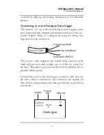
Connecting to a non-Decagon Data logger
5TE sensors for use with non-Decagon data loggers come
pre-configured with stripped and tinned lead wires at the cus-
tomer’s request. Below is a diagram showing the wiring con-
figuration for this connector.
5TE sensors with stripped and tinned cable option can be
made with custom cable lengths (up to 250ft) on a per-foot
fee basis. This option gets around the need for splicing wire (a
possible failure point).
Connect the wires to the data logger as shown, with the sup-
ply wire (white) connected to the excitation, the digital out
wire (red) to a digital input, the bare ground wire to ground as
seen below.
Digital out (Red)
Ground (Bare)
Excitation (White)
Sensor cable
Switched
3-15V DC
G
Supply
Digital
out
Ground
Datalogger
Digital
In

