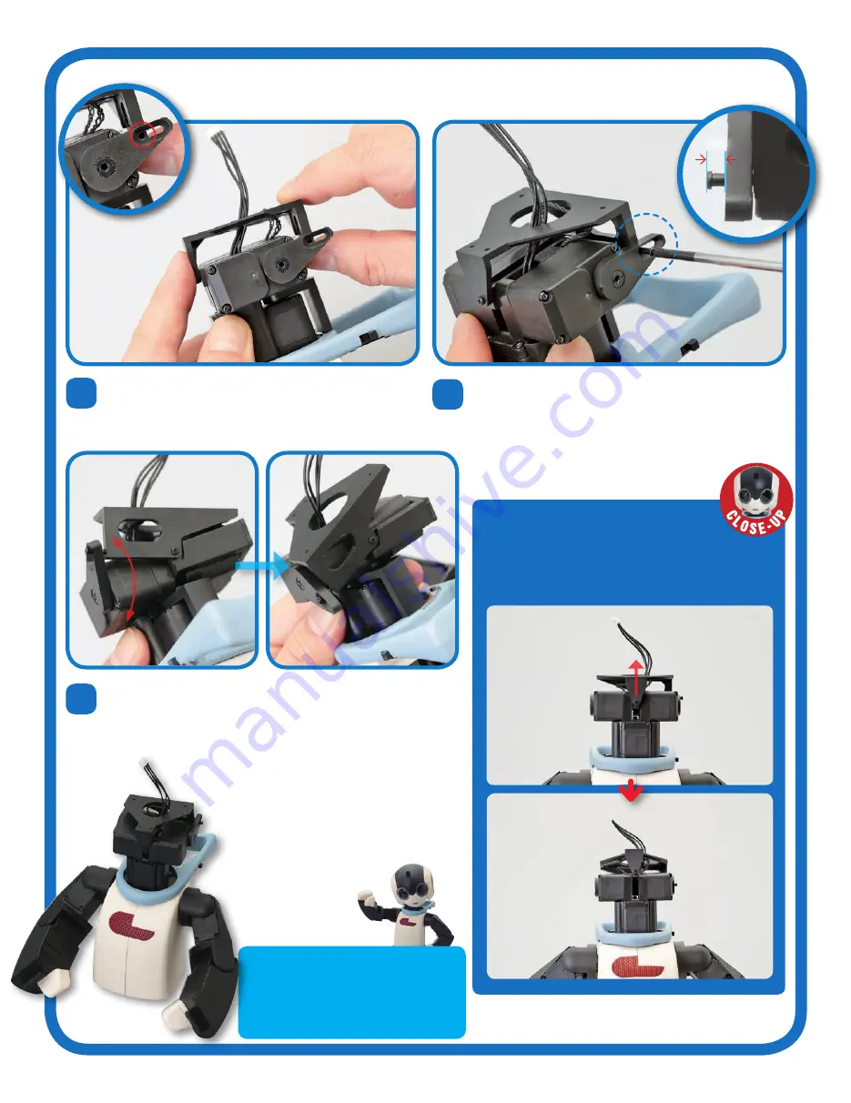
4mm
13
15
14
Level the head base so that the circled hole (inset) on its
rear left edge lines up with the elongated slot in the left-
hand servo horn.
The 4mm length of screw left is used to lift the side of the head
base up or bring it down, to tilt the base from side to side. Gently
test this a few times by hand to make sure that it moves freely, and
if not, go back and check the screws fitted in Steps 9, 11 and 14,
loosening them a little if necessary.
Fit an M2 x 12mm pan-head screw through the slot and into
the hole marked in the previous step. Turn this into the head
base, but stop when there is 4mm of the unthreaded section
left between the screw head and the servo horn (inset).
Remember, to see all of Robi’s assembly
stages, including this one, visit the
ModelSpace web page at:
www.model-space.com
Assembled
body and
head servos
Now that the head servos have their respective horns fitted
and are linked up to the head base, it will be easier to see
them in action, so you might like to run the test (described
in the previous stage) again.
Re-testing the head servos
341


