2 2 4 R R
Operating instructions and warnings
20
In case the gate structural features do not allow you to comply with the above force limits, it is possible
to use external safety devices inputs (terminals no. 11 and no. 12). “SIC1” and “SIC2” inputs can be
configured by setting properly parameter no. 18:
•P018 = 0 “rib” mode functioning: SIC1 = motor 1 rib input, SIC2 = motor 2 rib input. When one of the
two inputs is activated the movement direction of both motors is inverted. If one of the two inputs is acti-
vated during the slow-down phase, the activation is interpreted as stroke end thus stopping the movement
of the motor associated to that input.
•P018 = 1 “photoelectric barriers” mode functioning: you can use either “SIC1” or “SIC2” or both of
them, but remember to short-circuit the unused input. When one of the two inputs is activated, the move-
ment of both motors is stopped.
If you power external safety devices t 24VSIC output (terminal no.14), their proper working is
tested before each manoeuvre.
8.7
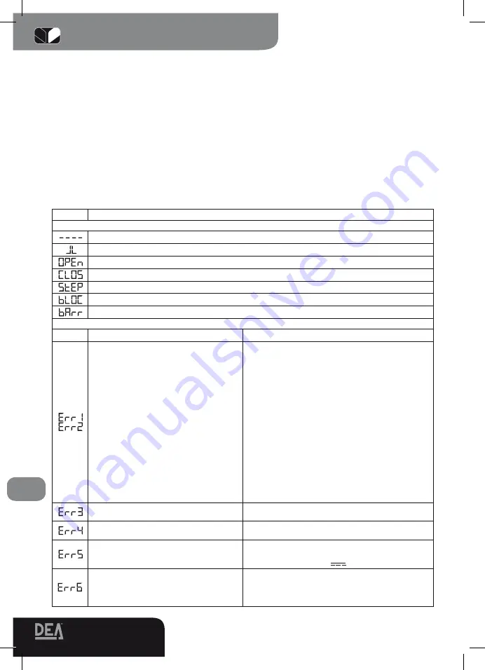
Messages shown on the display
224RR control board allows you to visualize on the display several messages concerning its working
status and any malfunction:
Message
Description
MESSAGES CONCERNING WORKING STATUS
Gate is closed
Gate is open
Opening under way
Closing under way
While in step-by-step mode, the control board awaits further instructions after a start command
Stop command received
Sic1 or sic2 activated while working in barrier mode
ERROR MESSAGES
Message
Description
Possible solutions
They point out that the gate has excee-
ded:
-(Err1), the max allowed number of
reversals (50) without ever reaching the
end of stroke (or stop) while closing;
-(Err2) the max number of uninterrupted
operations (10) of the anti-crush safety
device;therefore an “emergency maneu-
ver” is under way: the control board sets
the motors in a slow down phase and
searches the stops (or ends of stroke)
in order to reset the positioning system.
Once the stops (or ends of stroke) while
closing are found again the message
disappears and the control board awaits
further instructions “----” and then resu-
mes working normally.
In case the gate is not properly closed after the
emergency maneuver (maybe because of false
stops or obstacles due to mechanical frictions),
proceed as follows:
- Disconnect the power supply, check manually
that no particular frictions and/or obstacles are
present during the complete stroke of both leafs.
Leave both leafs half-open.
- Connect the power supply again and subsequen-
tly give a start pulse. At this point both leafs will
start to close in slow down phase until reaching the
stop (or end of stroke). Make sure that the maneu-
ver is properly completed. Adjust force and motor
speed values, if need be.
If the gate keeps working inappropriately try to
repeat the motor stroke memorization procedure
(see paragraph 8.2)
External photocells and/or safety devices
are activated or out of order
Make sure that all safety devices and/or photocells
installed are working properly.
The motors are not connected or it si-
gnals control board failure
Make sure that the motors are properly connected.
If the message reappears change the control board.
The control board power supply voltage
has exceeded the allowed range
Make sure the power supply voltage on the faston
connect. no. 29-30 is 22 V ~+/-10% and on fa-
ston no. 27-28 is 27 V +/-10%.
Possible motor overheating due to ob-
stacles hindering the doors movement.
The control board does not respond to
instructions
Remove any obstacle and wait until the message
“Err6” is replaced by message “bLOC” and the
control board responds to instructions again (a
few seconds)
Содержание 224RR
Страница 1: ......


