


18
De Gier B.V., Westlandseweg 9, 2291 PG WATERINGEN, THE NETHERLANDS,
+31 (0)174 292089, [email protected], www.degierdrivesystems.com
Versie 1 – 2020 / 03 / 01
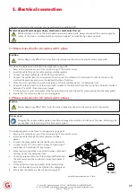
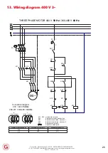
5. Electrical connection
5.3 Mains connection for DC-motors
Caution
Mains voltage may differ 10% at most from the voltage mentioned on the electric motor’s type plate.
The electrical diagram is available on request.
1. Remove the protective cover of the terminal strip of the electric motor.
2. Insert the cable through the gable gland.
3. Connect the green/yellow lead to the PE terminal (earth).
4. Connect the 24 VDC lead to terminal A1 and the neutral lead to terminal A2.
5. Move the motor gearbox to a position between both limit switches using a hexagonal tool.
6. Check the rotation direction of the output shaft relative to the limit switch and the control box. Swap the leads on A1
and A2 if necessary.
7. Fit the protective cover and gasket of the terminal strip back onto the electric motor and tighten the cable gland.
8. Ensure that the cables are clear of any moving parts.
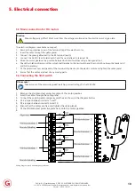
5.4 Connecting the limit switch
Please note!
Take account of the maximum (peak) switching current rating of 6 A at 250 VAC
1. Remove the stainless-steel protective plate of the motor gearbox
2. Insert the cable through the cable gland
3. Connect the working and emergency switches, as shown in the diagram below
4. Fit a jumper between contacts 1 and 7
5. Fit a jumper between contacts 6 and 10
6. Ensure that the cables are free and tighten the cable glands.
7. Fit the stainless-steel protective plate back onto the motor gearbox.
8.
Wiring diagram work- and emergency switches


