background image


18


The scratch guard may be installed on the clamping cup to protect aluminum rims from being marred, but should not be used on steel 

wheels.


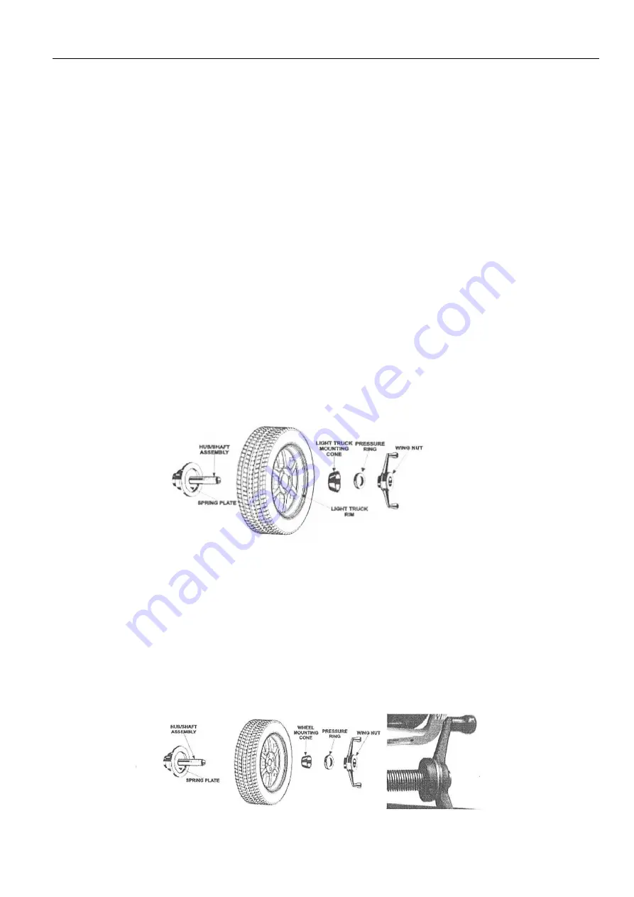
FRONT CONE MOUNTING PROCEDURE


This procedure utilized a tapered cone inserted from the front side of the wheel instead of the backside as previously described.


Select the proper wheel-mounting cone by placing it in the center bore of the wheel to be balanced.    Choose the cone that contacts 

the wheel nearest the center of the cone.   


Mount the wheel with the inner rim facing the balancer.    Place the wheel-mounting cone on the spindle with the small end of the cone 

facing the front of the wheel.


Install  the  wing  nut  and  pressure  ring  assembly  onto  the  spindle  shaft  against  the  wheel  and  secure  the  entire  assembly  by  firmly 

tightening the wing nut.   


Heavy wheel centering may benefit by pulling the tire away from the hub face at top dead center while tightening the wing nut.    This 

helps the wheel to overcome gravity against the hub or spacer.


PRESSURE RING


The pressure ring should be used to prevent the wing nut from directly contacting an adaptor or a cone. 


  It may also be used in place of a pressure cup if space is limited between the wheel and the end of the spindle.


TIRE TECH INFORMATION/GENERAL TIRE INFORMATION


Содержание B917

Страница 1: ...1 B917 WHEEL BALANCER READ THIS ENTIRE MANUAL BEFORE OPERATION BEGINS Serial No __________ Model No ___B 917___...

Страница 2: ...rect or indirect damage to the equipment The equipment should be installed on the stable ground not wooden pallet otherwise not accurate Keep the back panel 0 6M away from the wall for good ventilatio...

Страница 3: ...ssembly 1 3 Controls and components 3 4 Indication and use of wheel balancer 6 5 Self calibration of wheel balancer 10 6 Errors 11 7 Self diagnoses 12 8 Setting machine 12 9 OPT function 13 10 Spare p...

Страница 4: ...o clock or 12 o clock position to add weight Statistic and dynamic balancing ALU programs for alloy rims or special shaped Self diagnoses easy to find the problem Apply to steel and aluminum alloy ri...

Страница 5: ...tor for fastening wheel with central bore see below picture 2 5 Install wheel Clean wheel take off counterweights check pressure of wheel Choose the way of installation according to the type of wheel...

Страница 6: ...Balancing mode Operation Add weights Standard Default Turn on machine Input a b d value Start spin after spin stop Clip on weights on both sides of rim edge ALU2 1 Turn on machine 2 Input a b d value...

Страница 7: ...n machine 2 Press ALU button indicator lit up 3 Input aI aE d value 4 Start spin after spin stop Add adhesive weights on the two positions gauge head touch Static mode for motorcycle wheels 1 Turn on...

Страница 8: ...dle nut wheel quick handle nut Attention May add a wheel and hold the wheel to help install the thread hub When installing or taking off wheel do not let wheel move on the shaft to avoid scratching sh...

Страница 9: ...position where to mount the counterweights 12 o clock position outside as Fig 3 clip the counterweight Fig 3 4 1 7 Anticlockwise moving wheel slowly the displays with left LED s lit up full indicate...

Страница 10: ...clock position 9H Off or 9 o clock 9H On position outside as Fig 6 add the counterweight Fig 6 4 2 6 Anticlockwise moving wheel slowly the displays with left LED s lit up full indicate the correct an...

Страница 11: ...rim Fig 9 4 3 3 Put down the guard and press to perform a measuring spin 4 3 1 12 o clock position to add weight Set SLC as OFF according to 8 1 Anticlockwise moving wheel slowly until the right LED...

Страница 12: ...e wheel is balanced Fig 22 Self calibration of wheel balancer Do the self calibration whenever you think the balancer is not accurate The 100g weight must be accurate Turn on balancer install a medium...

Страница 13: ...locked tightly 2 Position pick up board problem 1 Lock tightly 2 check or change position pick up board 3 1 No enough pressure in wheel 2 Wheel distortion 1 Add proper pressure in wheel 2 Check wheel...

Страница 14: ...xperienced Install wheel input a b d value 1 Press comes 2 Put down safe guard and press comes 3 With the help of tire changer change the rim and rubber 180 degree reference 4 Then put down safe guard...

Страница 15: ...he non rounded amount of imbalance on each weight plane Repeat this procedure four times without removing the wheel to verify the balancer can repeat measurements within 0 05 ounce per plane If it doe...

Страница 16: ...d hub assembly must be replaced BALANCER MOUNTING METHODS MOUNTING THE WHEEL ON THE VEHICLE Since today s vehicles are more sensitive to road feel it is critical to be aware of how the wheel mounts on...

Страница 17: ...DURE Select the proper wheel mounting cone by placing it in the center bore of the wheel to be balanced Select the cone that contacts the wheel nearest the center of the cone Place the wheel mounting...

Страница 18: ...ace the wheel mounting cone on the spindle with the small end of the cone facing the front of the wheel Install the wing nut and pressure ring assembly onto the spindle shaft against the wheel and sec...

Страница 19: ...ge tread blocks subject to chunking 7 Lug centric wheels are notoriously hard to balance on common hub centric balancers and are found with many different rim manufacturers Toyota also locates the whe...

Отзывы: