5
• Insert the plug and then rotate ¼ turn clockwise as
shown in
figure 1.3
.
Figure 1.3
• Once the pump is pressurized the plug will pop
up slightly engaging the security latch (
figure
1.4
), thus preventing accidental removal. While
the plugs can be removed under pressure, the
operator must intentionally push the plug in and
then, whilst still holding the plug in, twist counter-
clockwise on the plug. It is possible to abort plug
removal part way through the process.
Figure 1.4
Gap
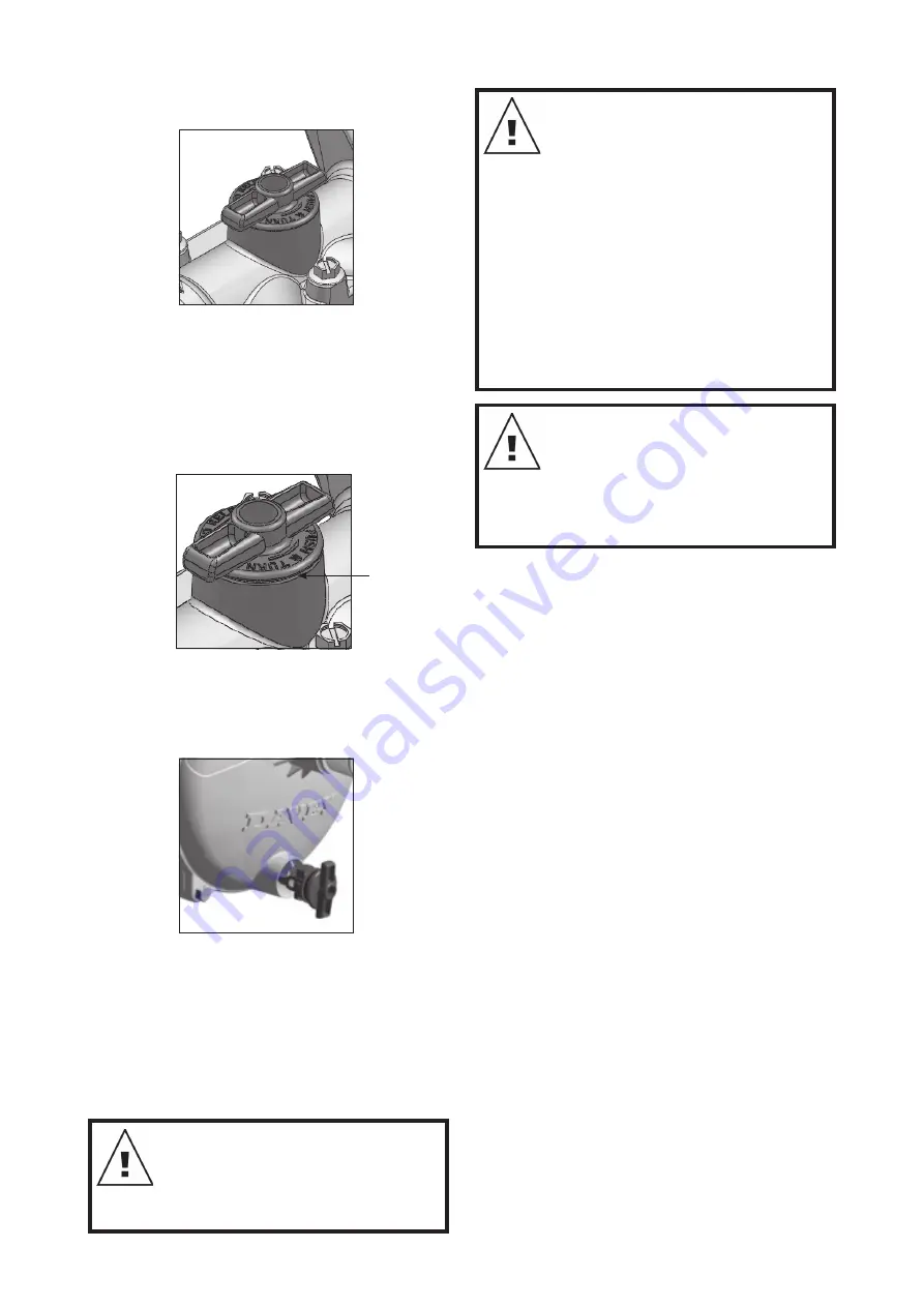
1.5 Drain plug
The drain plug fitment is like the priming plug.
However, to insert the drain plug the plug handles
start in the vertical position as shown in
figure 1.5
.
Figure 1.5
Keep the plug and it’s surround free from sand and
grit. Occasionally apply a suitable silicon-based
rubber grease (petroleum-based greases are not
acceptable) to the o-ring. The Firefighter pump drain
plug is identical in operation. Both plugs are available
with a 1/4” BSP taping to facilitate the fitment of
pressure gauges or automatic drain valves etc.
2. PUMP WARNINGS
ATTENTION: The Firefighter pump
may contain hot liquid under
pressure. The Firefighter pump body
should always be full of water when
operating and must not be allowed to
run dry for extended periods.
IMPORTANT: Check that there is
water flow through Firefighter pump
when running, as insufficient flow
can cause damage, not covered by
warranty. If a Firefighter pump has
been allowed to run at closed (or
“dead”) head, do not open any valves
of priming plugs until the pump
casing has cooled.
When transporting your Firefighter
pump, water from the casing may leak
back past the priming flap. Before
attempting to self-prime the Firefighter
pump you may need to check that the
casing is still full of water.
ATTENTION: In the event of fire
damage to the Viton elastomers
(“rubber”), consult your Davey dealer
regarding safe handling of burnt
Viton components. Burnt Viton emits
a dangerous acid, which can cause
serious health effects.
3. CARE AND MAINTENANCE
3.1 Pump and pipework
Run the pump every week or so during the fire
season to ensure it and associated pipework and
fittings are in good working order. This will also help
turnover the fuel and make sure the lubricating oil
is circulated around the engine. Ensure the water
source is free of leaves and sticks etc. which may
block inlet strainers and obstruct the water flow to
the pump.
Check for pipe leaks and the correct operation of
all valves connecting the Firefighter pump to the
water source and on the discharges. Air leaks on
the suction line are the number one cause of pump
problems. Make sure all rubber gaskets and seals
are in good order.
3.2 Pump operation
High performance can be obtained from a Firefighter
pump if the engine speed is increased. However,
we do not recommend the Firefighter pump be
operated over 3,600rpm for extended periods, as
this may overload the engine and reduce its working
life. Operating the engine at full throttle for extended
periods will shorten engine life and may result in
premature failure. For operations such as irrigation
or dam and tank filling, the throttle should be closed
to around 3/4 maximum. This should correspond to
around 3,000rpm. The exception to this is the diesel
models 5148Y, 5248YEV and 5210YE/HP. These
models are continuously rated to 3,600rpm.
Note: special consideration applies to 5150P and
5250P models. See section 4.7.
Содержание Firefighter 5148YEV
Страница 26: ...26 NOTES...
Страница 27: ...27...


