24
7.2
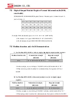
Digital Output Module Register Format Information (0x2000,
rewritable)
GFDO-RM01N/ GFDO-RM02N Register Format: Channel open-1; channel closed - 0;
reserved value - 0.
Bit15 Bit14 Bit13 Bit12 Bit11 Bit10 Bit9
Bit8
Ch44 Ch43 Ch42 Ch41 Ch34 Ch33 Ch32 Ch31
Bit7
Bit6
Bit5
Bit4
Bit3
Bit2
Bit1
Bit0
Ch24 Ch23 Ch22 Ch21 Ch14 Ch13 Ch12 Ch11
Example: With all channels open: 1111 1111 1111 1111 (0xFF 0xFF);
with channel 1 to 8 open: 0000 0000 1111 1111 (0x00 0xFF);
with all channels closed: 0000 0000 0000 0000 (0x00 0x00).
7.3
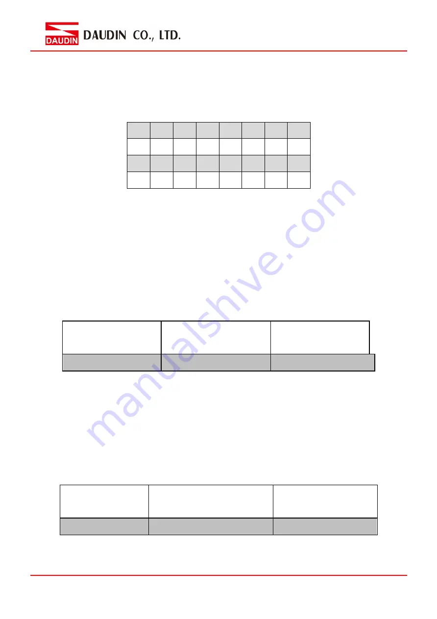
Modbus function code 0x10 Demonstration
I.
Use Modbus RTU/ASCII to write in single-chip digital output module registers
Modbus function code
Transmission example
(ID:0x01)
Respond example
(ID:0x01)
0x10
01 10 20 00 00 01 02 FF FF
01 10 20 00 00 01
※
In this example, we are writing in “0x2000” with the I/O module ID of “01”
※
When not using control modules for communications, the registers will be at
0x2000
II.
Use Modbus RTU/ASCII with control modules to write in digital output
registers
Modbus function
code
Transmission example
(ID:0x01)
Respond example
(ID:0x01)
0x10
01 10 20 00 00 01 02 FF FF
01 10 20 00 00 01
※
In this example, we are writing in “0x2000” with the control module ID of “01”
※
When using control modules for communications, the registers will start at 0x2000

