background image


10 

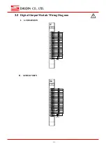
3.2 

Digital Output Module Wiring Diagram 

I.


GFDO-RM01N 

L

24V DC

L

L

L

L

L

L

L

L

L

L

L

L

L

L

L


II.


GFDO-RM02N 

L

24V DC

L

L

L

L

L

L

L

L

L

L

L

L

L

L

L


Содержание iO-GRID M GFDO-RM01N

Страница 1: ...iO GRID M Digital Output Module User s Manual 2301TW V3 0 0...

Страница 2: ...m 10 4 Module Installation Disassembly 11 4 1 Installation 11 4 2 Removal 12 5 iO GRID M Series Introduction 13 5 1 iO GRID M Components 13 6 I O Module Parameter Settings and Introduction 16 6 1 I O...

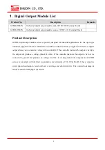
Страница 3: ...within enclosures supplied in the field A digital output allows you to control a voltage with a controller If the controller instructs the output to be high the output will produce a voltage about 24...

Страница 4: ...NSTALLATION THAT THE SAFETY OF ANY SYSTEM INCORPORATING THE EQUIPMENT IS THE RESPONSIBILITY OF THE ASSEMBLER OF THE SYSTEM L INSTALLATION DE TOUT SYST ME INT GRANT CET QUIPEMENT EST LA RESPONSABILIT D...

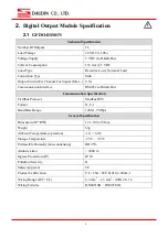
Страница 5: ...ace RS485 via Dinkle Bus Communication Specification Fieldbus Protocol Modbus RTU Format N 8 1 Baud Rate Range 1200 1 5 Mbps General Specification Dimension W D H 12 x 100 x 97mm Weight 69g Ambient Te...

Страница 6: ...le Bus Communication Specification Fieldbus Protocol Modbus RTU Format N 8 1 Baud Rate Range 1200 1 5 Mbps General Specification Dimension W D H 12 x 100 x 97mm Weight 69g Ambient Temperature operatio...

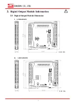
Страница 7: ...7 3 Digital Output Module Information 3 1 Digital Output Module Dimension I GFDO RM01N II GFDO RM02N Unit mm Unit mm...

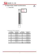
Страница 8: ...ng Connector definitions Terminal block labeling Connector definitions 11 Channel 1 31 Channel 9 12 Channel 2 32 Channel 10 13 Channel 3 33 Channel 11 14 Channel 4 34 Channel 12 21 Channel 5 41 Channe...

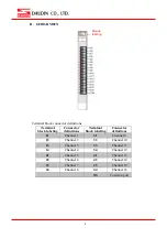
Страница 9: ...ns Terminal block labeling Connector definitions 11 Channel 1 31 Channel 9 12 Channel 2 32 Channel 10 13 Channel 3 33 Channel 11 14 Channel 4 34 Channel 12 21 Channel 5 41 Channel 13 22 Channel 6 42 C...

Страница 10: ...10 3 2 Digital Output Module Wiring Diagram I GFDO RM01N L 24V DC L L L L L L L L L L L L L L L II GFDO RM02N L 24V DC L L L L L L L L L L L L L L L...

Страница 11: ...to the arrow on the DIN rail II Press the module down and the metal clamp will slide thanks to its spring mechanism and grab on the other side of the DIN rail Continue to push down until the metal cl...

Страница 12: ...12 4 2 Removal I Use a screwdriver to pull the metal hook sideways and detach the module from the DIN rail II Remove all modules from the DIN rail in reverse order of installation...

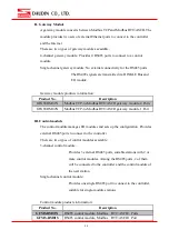
Страница 13: ...bus TCP Please choose products and factory controllers to figure your system based on your communication protocol 5 1 iO GRID M Components I DINKLE Bus Rail 1 to 4 are defined for power supply and rai...

Страница 14: ...ts GFGW RM02N Modbus TCP to Modbus RTU ASCII gateway module 1 Port III Control module The control module manages I O modules and sets up the configuration Provides external RS485 ports to connect to t...

Страница 15: ...g input module 0 10VDC GFAI RM20 4 channel analog input module 0 20mA GFAI RM21 4 channel analog input module 4 20mA GFAO RM10 4 channel analog output module 10VDC GFAO RM11 4 channel analog output mo...

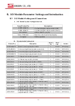
Страница 16: ...mA 1 115200 RTU 8 N 1 GFAI RM21 4 channel analog input module 4 20mA 1 115200 RTU 8 N 1 GFAO RM10 4 channel analog output module 10VDC 1 115200 RTU 8 N 1 GFAO RM11 4 channel analog output module 10 10...

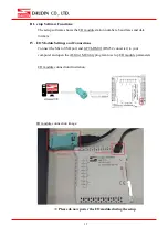
Страница 17: ...formats IV I O Module Settings and Connections Connect the Micro USB port and GFTL RM01 RS232 converter to your computer and open the iO Grid M Utility program to set up I O module parameters I O modu...

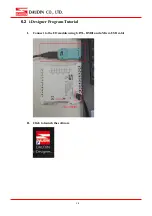
Страница 18: ...18 6 2 i Designer Program Tutorial I Connect to the I O module using GFTL RM01 and a Micro USB cable II Click to launch the software...

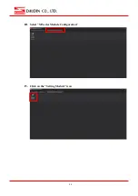
Страница 19: ...19 III Select M Series Module Configuration IV Click on the Setting Module icon...

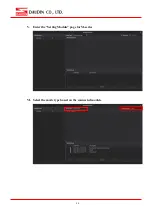
Страница 20: ...20 V Enter the Setting Module page for M series VI Select the mode type based on the connected module...

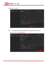
Страница 21: ...21 VII Click on Connect VIII Set up I O modules station numbers and communication format must click on Save after changing them...

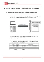
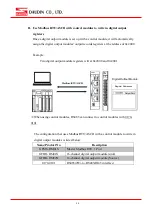
Страница 22: ...odule register to be written is 0x2000 With no control module RS485 s physical wire must be connected with an adapter to send the signal to the Dinkle Bus The configuration that uses Modbus RTU ASCII...

Страница 23: ...sters will at 0x2000 and 0x2001 When using control modules RS485 can connect to control modules with 0170 0101 The configuration that uses Modbus RTU ASCII with a control module to write in digital ou...

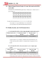
Страница 24: ...Demonstration I Use Modbus RTU ASCII to write in single chip digital output module registers Modbus function code Transmission example ID 0x01 Respond example ID 0x01 0x10 01 10 20 00 00 01 02 FF FF 0...

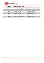
Страница 25: ...ssion example ID 0x01 Respond example ID 0x01 0x01 01 01 00 00 00 10 00 01 02 FF FF 0x05 01 05 00 00 FF 00 01 05 00 00 FF 00 0x06 01 06 20 00 FF FF 01 06 20 00 FF FF 0x0F 01 0F 00 00 00 10 02 00 01 01...

Отзывы: