background image

29 


After  the  size  and  position  of 

start  and  stop 

windows

motion 

type  and 

speed  mode 

are 

configured,  you  can  start  the  animation  by  clicking 

Play 

button.


Note

The motion speed range is from 1-15.  


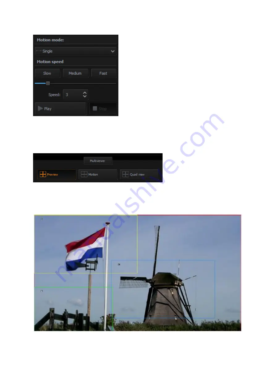
Multiviewer – Preview on the Monitor 

Three  Multiview  modes  including  “Preview”,  “Motion”  and  “Quad  View”  are  shown  as 
following diagram.   


Preview 

– Four rectangles at their respective Start positions are visible on the live input. In 

the diagram below, frame window 1 covers the entire screen. Press the “Play” button allows 
the four Frames to move simultaneously.


Motion preview– Press one of the Frame tabs allows users to preview the “Start Position” 
and “End Position” by the connected external monitor. The start position and end position 

Содержание KMU-100

Страница 1: ...PROCESSOR Instruction Manual ...

Страница 2: ...24 You can set a graphical background for the gray workspace of the Central Work Area and the graphical background should help you better position the frame windows 25 Frame 1 2 3 and 4 Setting Control Area 25 4 3 TOOL BAR 32 5 HOW TO OPERATE THE KMU 100 33 5 1 HOW TO OPERATE THE KMU 100 BY THE CONTROL SOFTWARE 33 5 2 HOW TO USE THE RMC 185 TO CONTROL THE KMU 100 39 5 2 1 HOW TO CONNECT THE RMC 18...

Страница 3: ... MENU EXIT 66 FN2 INPUT A SOURCE ASSIGNMENT INPUT A SOURCE 66 FN3 INPUT B SOURCE ASSIGNMENT INPUT B SOURCE 66 FN4 OUTPUT FORMAT SELECTION OUTPUT FORMAT 66 FN5 AUDIO OUTPUT 67 FN6 GENLOCK SETTING GENLOCK SET 67 FN7 GENLOCK STATUS DISPLAY GENLOCK STATUS 67 FN8 SELECTION OF SDI 3G TYPE SDI 3G TYPE 67 FN9 OUTPUT ASSIGN 67 FN10 LIMIT 67 FN11 EXTERNAL MOTION TRIGGER SETTING TRIGGER SET 67 FN12 KMU 100 F...

Страница 4: ...mplete This manual may contain typing errors omissions or incorrect information Datavideo Technologies always recommend that you double check the information in this document for accuracy before making any purchase decision or using the product Datavideo Technologies is not responsible for any omissions or errors or for any subsequent loss or damage caused by using the information contained within...

Страница 5: ...f you are not sure of the type of power available consult your Datavideo dealer or your local power company 8 Do not allow anything to rest on the power cord Do not locate this unit where the power cord will be walked on rolled over or otherwise stressed 9 If an extension cord must be used with this unit make sure that the total of the ampere ratings on the products plugged into the extension cord...

Страница 6: ... or water is not covered under warranty Viruses and malware infections on the computer systems are not covered under warranty Any errors that are caused by unauthorized third party software installations which are not required by our computer systems are not covered under warranty All mail or transportation costs including insurance are at the expense of the owner All other claims of any nature ar...

Страница 7: ...onserve natural resources and ensure that it is recycled in a manner that protects human health and the environment For more information about where you can drop off your waste equipment for recycling please contact your local city office your household waste disposal service or the shop where you purchased the product CE Marking is the symbol as shown on the left of this page The letters CE are t...

Страница 8: ...hange its size while it is animated featuring the virtual digital zoom 1 1 Functions and Features The KMU 100 is an advanced video converter that allows processing and conversion of UHD signals with the resolution of 3840x2160 12G SDI or HDMI 2 0 into four or eight different high quality streams at resolutions up to Full HD The KMU 100 offers the user two independent conversion channels The device...

Страница 9: ...etermine the output content is nothing more than a simple positioning of a frame rectangle in the MultiViewer preview for a given channel Each of the frame rectangles is marked with a different border color For one of the frames you can scale the signal from full 4K resolution to Full HD and there is also up and down scaling zoom possible for all other outputs The output area position of each fram...

Страница 10: ...tproduction The KMU 100 capabilities are perfect for video postproduction compared to other similar products on the market The video material is recorded with one or two video cameras at 4k resolution With the KMU 100 you can not only change the composition but also the shots The end result will resemble the use of several cameras With the switcher connected the transitions between the output imag...

Страница 11: ...he KMU 100 processes the signal in real time you obtain the effect of 8 high quality mobile video cameras but without their actual movement In this way the converter provides new opportunities and possibilities to cut down the costs by reducing the number of video cameras and the cables used and at the same time increases precision and quality in capturing all important details ...

Страница 12: ...KMU 100 users to download the DV Link application for free The technical specifications manual and the download link can be found on the product page 3 1 Hardware Connection Prior to the use of the KMU 100 you must first set up the hardware system and configure the IP settings between the PC and the KMU 100 The subsections below will guide you through the connection process step by step 1 First of...

Страница 13: ...een the KMU 100 and the PC 3 2 Launching DV Link Application After the DV Link application is downloaded and installed on your computer simply click the DV Link desktop icon to open the application While DV Link application is loading a screen with a progress bar at the bottom will be displayed as shown in the diagram below ...

Страница 14: ...w The DV Link application window can be divided into 4 areas listed as follows 1 Tool Bar 2 Available Networks 3 Available Devices 4 Single device Control Area KMU 100 Tool Bar A Tool Bar is located at the upper left corner of the screen where you will be able to find three main options File Options and Help ...

Страница 15: ...the language of the application English Chinese PRC Chinese Taiwan Polski Help this option contains the following sub options About End User License Agreement EULA Version QR Code Provides the link to the KMU 100 product page Available Networks area In this area the available networks are displayed as shown in the diagram below ...

Страница 16: ...16 After moving the cursor over and clicking on a given network icon the available devices in this network will appear in the Available Devices area ...

Страница 17: ...etwork settings are shown on the bottom of the rightmost column which is shown as above mentioned diagram Users can load one of your default settings to the selected KMU 100 device by one of the four Preset keys Generally speaking users can find all KMU 100 devices within the same network area by the DV Link software After the devices are connected users can load the Preset settings and then they ...

Страница 18: ... bar at the bottom will be displayed 4 1 App Window Descriptions Connection Tab The Connection tab allows you to define input signals connected to Channel A and Channel B It is also possible to use the signal from Input A to process in Channel B and vice versa i e processing of Input B in Channel A After clicking the Connection tab you will see a diagram with visualization of necessary cable conne...

Страница 19: ...lanations of the Menu area is in later parts of the manual 2 Connection Graphics area The Connection Graphics Area is basically a graphical visualization of the rear panel of the KMU 100 device with all its available inputs and outputs The active status and the introduced changes to the inputs and outputs are graphically shown on the screen in the form of arrows orange icons In fact the active inp...

Страница 20: ...rmat Resolution FPS and Mode are displayed as illustrated in the diagram above The other ports shown in the Connection Graphics Area are listed as follows Port 2 x HDMI Video Output HDMI type A supporting 1080p60 For KMU 100 Those two ports allow users to connect to two monitors to show the Multiview screens of the Channel A and Channel B For KMU 100 Those two ports allow user to connect to two mo...

Страница 21: ... Moreover it allows users to control the KMU 100 by the VISCA Protocol Port RS 232 input is currently unused DC power supply socket 3 Input Output Signals area allows you to configure the KMU 100 device I O Input Signal Configuration You can select an input signal option from the Signal Input A drop down list as shown below as well as the Signal Input B drop down list There are 4 input signal opti...

Страница 22: ...e diagram below After configuring Signal Input A you can do the same with Signal Input B There are 4 options in the Signal Input B drop down list 4x SDI 1x SDI HDMI Input Signal A When there is no input source for the Input B users can copy the signal source of the Input A to the Input B Please select Input Signal A option from the Signal Input B drop down menu ...

Страница 23: ...e Input A to the Input B For example 8 frame windows instead of 4 Output Signal Configuration There are several output signal format options in the Output Format drop down list The available formats are SD PAL NTSC SD 16 9 PAL NTSC 720p 50 59 94 60 1080i 50 59 94 60 1080p 25 29 97 30 1080p 50 59 94 60 ...

Страница 24: ...m below 1 Menu Area 2 Central Work Area 3 Frame 1 2 3 and 4 Setting Control Area 4 Multiviewer Preview on the Monitor Menu Area Channel A B tab turns orange indicating that the work is being done on this screen window Clicking the Channel B tab will switch to the Channel B screen window Central Work Area In this area the frame windows are defined and sent to the corresponding outputs To improve UI...

Страница 25: ...urther A double click on the edited window will switch it to the max available size and the second double click will restore it to its previous size Aspect ratio is defined by the output resolution and automatically applied to frame window definition You can set a graphical background for the gray workspace of the Central Work Area and the graphical background should help you better position the f...

Страница 26: ...n and the size of the Start and Stop rectangles can be defined using the mouse cursor or by entering the position coordinates in the Frame Setting Area Current position and size and Destination position and size If you want to set the final window position exactly in the place where the start window is you can simply click the From Current button After the From Current button is clicked you should...

Страница 27: ...27 Stop rectangle is drawn in dash mode In the picture below you can see that the Start rectangle is indicated by a short arrow and the Stop rectangle is indicated by a longer arrow ...

Страница 28: ...l movement i e Start Stop Stop Start Start Stop and so on pendulum swing motion Trig Double Ping Pong This can trigger dual Swing cyclical movement i e Start Stop Stop Start Start Stop and so on Note You will see the animation as virtual movement of the camera shot In addition to changing the window position you can define its size as well thereby effectively realizing a virtual zoom function As s...

Страница 29: ...ding Preview Motion and Quad View are shown as following diagram Preview Four rectangles at their respective Start positions are visible on the live input In the diagram below frame window 1 covers the entire screen Press the Play button allows the four Frames to move simultaneously Motion preview Press one of the Frame tabs allows users to preview the Start Position and End Position by the connec...

Страница 30: ...m Please press the Play button and then users can see that the Frame moves from the start position to the end position Quad view In the Quad View mode preview of contents of the four outputs is displayed on the monitor as shown in the diagram below ...

Страница 31: ...steps for saving the Preset settings 1 Please press the Save Preset button to open the window for saving preset 2 Please select the Preset 1 Preset 2 Preset 3 or Preset 4 on the left side of the pop up window After that please press the Save button for saving the current settings into the corresponding Preset Please follow following steps for recalling the Preset settings 1 What you have to do is ...

Страница 32: ...lick on the respective main options File Exit Quit the application Options Language Select the language English Chinese PRC Chinese Taiwan Polski Configuration Additional application settings Information about the device SDI 3G output type Firmware Network configuration Triggers Temperatures Help About About KMU 100 End User License Agreement EULA Device Version A link to the KMU 100 product page ...

Страница 33: ... 3 1 Hardware Connection Moreover please confirm that the HDMI or SDI input source is connected successfully 2 Please open the DV Link and the KMU 100 control software according to 3 2 Launching DV Link Application 3 After the KMU 100 control software is launched the main interface is shown as following diagram Please select the input source interface and the input source format from the drop down...

Страница 34: ...the same way for Channel B for showing the Channel A setting interface which is shown as following diagram 5 Please press the Load Background button for loading the screen which is shot by the camera which is connected to the Channel A Input The screen will be shown as following diagram ...

Страница 35: ... is an external connected monitor which is connected to the MULTIVIEW A HDMI interface which is located on the rear panel of the KMU 100 users can see the No 5 to No 8 Preview screens on the external connected monitor However if there is one external connected monitor only users can press the Swap button for showing the No 5 to No 8 Preview screens on the same external connected monitor 960 x 540 ...

Страница 36: ...l B button and then press the Motion button users can see the selected Frame to be shown in dotted line from the external connected monitor When users want to adjust the motion effect please follow following steps Please make sure that the input channel Channel A or Channel B and Frame that you want to adjust are selected Please adjust your desired parameters including Current position and size De...

Страница 37: ...from the external connected monitor When users want to adjust the motion effect please follow following steps Please make sure that the input channel and Frame that users want to adjust are selected properly Please adjust your desired parameters including Current position and size Destination position and size Horizontal position Vertical position Width 1 1 960 x 540 960 x 540 The solid rectangula...

Страница 38: ... Stop button How to Save Current Settings by Preset for Recalling Directly in the Future The KMU 100 control software allows users to save current settings in Preset for recalling directly in the future Please follow following steps for saving and recalling the Preset settings How to Save Current Settings in Preset At first please make sure that your desired settings including Horizontal position ...

Страница 39: ... two HDMI cables to connect the two external connected monitors to the MULTIVIEW OUTPUT B and MULTIVIEW OUTPUT A interfaces which are located on the rear panel of the KMU 100 The MULTIVIEW OUTPUT B interface is located on the upper side for outputting the Multiview preview screens of the Frame5 Frame6 Frame 7 and Frame 8 The Multiview OUTPUT A interface is located on the lower side for outputting ...

Страница 40: ...ame view 6 1 Notices for Device Setup The RMC 185 is designed to control the KMU 100 Therefore before pairing the RMC 185 with the KMU 100 the user should first ensure that the two devices are installed of the two pieces of firmware as listed below KMU 100 V134E7 RMC 185 V1 006 After the devices have been successfully upgraded to their corresponding firmware connect the power to the RMC 185 throug...

Страница 41: ...LCD panel Menu Control Dials The RMC 185 configuration menu can be entered and browsed using these dials Push to select a specific item and rotate to browse the selected menu option Multiviewer Mode Select P Preview Press to display current position of the selected frame M Motion Press to display motion of the selected frame playback of the motion from ...

Страница 42: ...same button for about 2 seconds will stop motion Button LED flashes while the motion is in progress When the motion is stopped the button LED will stop flashing and turn to constant lit PTZ Joystick Control Note Before attempting to use the joystick to PAN TILT or ZOOM a selected frame first make sure the LOCK button is not enabled PAN Move the joystick left or right to pan the selected frame from...

Страница 43: ...s STORE Pressing this button enters the RMC 185 into STORE MODE When activated this allows the current device setting to be stored in a chosen Preset Button by pressing the corresponding Preset Button Press again to exit STORE MODE PRESETS The preset buttons may be used to store up to four device settings Each button corresponds to one stored device preset Simply press the button to recall the sav...

Страница 44: ... on the RMC 185 rear to connect the KMU 100 The communication protocol is RS 422 so use an RJ 45 to DSub cable to connect the RMC 185 to the RS 422 port located on the KMU 100 rear panel DC In Socket Connect the supplied 12V 0 5A PSU to this socket The connection can be secured by screwing the outer fastening ring of the DC In plug to the socket Power On Off Switch Switches the device ON OFF ...

Страница 45: ...ed on the LCD panel Press the dial to select a particular option and rotate the dial to browse through the option items FN1 Exit FN2 Input A Source 1 x SDI 4 x SDI HDMI Clone FN3 Input B Source 1 x SDI 4 x SDI HDMI Clone FN4 Output Format PAL NTSC PAL 16 9 NTSC 16 9 720p50 720p59 94 720p60 1080p25 1080p29 97 1080p30 1080i50 ...

Страница 46: ...e Termination Enable Disable FN6 Genlock Status Ref Present Loose Lock Unlock Format Detected video format Up to 1080p60 FN7 SDI 3G Type Type A Type B FN8 Multi Swap ON OFF FN9 Multi SDI ON OFF FN10 Trigger Set Motion No 1 8 Trigger Level Low High FN11 KMU 100 Ver FPGA HARDWARE NIOS ARM ...

Страница 47: ...I 2 0 Clone Input B as a source FN3 Input B Source Assignment Input B Source In this option you may select a source for input B image processing The available interfaces are 1xSDI SDI video interface up to 12G SD is not supported 4xSDI quad SDI video HDMI HDMI 2 0 Clone Input A as a source FN4 Output Format Selection Output Format There are many video output formats available for selection The ava...

Страница 48: ...output channel on the KMU 100 works as a multiviewer output FN10 External Motion Trigger Setting Trigger Set In this option you will be able to configure the external motion trigger method Motion 1 8 can be controlled by an external device using the level trigger method You can either set the trigger method to low level trigger or high level trigger FN11 KMU 100 Firmware Version Display KMU 100 Ve...

Страница 49: ... device setting to one of the preset buttons To store a device setting 1 Adjust the frame positions using the joystick 2 Push the STORE button and it will turn red 3 Press a preset button to save the current device setting 4 The selected preset button will remain ON for 2 3 seconds and the button LED will be turned OFF after the device setting is successfully saved ...

Страница 50: ...ocated in the middle of the MULTIVIW 1 or MULTIVIEW 2 button row 2 Press one of the STOP row buttons buttons 1 to 8 to select a frame to adjust its motion setting 3 Use the joystick to zoom the frame and adjust its start position fine border frame 4 Press the button one of the STOP row buttons 1 to 8 selected at Step 2 again ...

Страница 51: ...order frame 6 Press the STORE button constantly lit 7 Use the left knob below the LCD screen to set the Frame Motion Mode and the right knob to set the Frame Motion Speed 8 Press the button one of the STOP row buttons 1 to 8 selected at Step 2 again to trigger the frame motion ...

Страница 52: ...f the KMU 100 2 Please use two HDMI cable to connect the two external monitors to the MULTIVIEW OUT B and the MULTIVIEW OUT A interface The MULTIVIEW OUT B interface is located on the upper side for the MULTIVIEW PREVIEW screen output The MULTIVIEW OUTPUT A interface is located on the lower side for the PROGRAM screen output 3 Please use an RJ 45 to RS 422 adapter cable to connect from the KMU REM...

Страница 53: ...tings Full remote control of the KMU 100 via RS 422 connection An LCD display showing setup menu options Two Multiviewer modes Switcher and KMU modes Compact design for easy installation 10 3 Notices for Device Setup The RMC 185 is designed to control the KMU 100 Therefore before pairing the RMC 185 with the KMU 100 the user should first ensure that the two devices are installed of the two pieces ...

Страница 54: ...54 11 System Diagram of the RMC 185 and KMU 100 Connection ...

Страница 55: ...is booted up the upper row of the LCD screen should show RMC 185 for KMU 100 The bottom left of the LCD screen shows the frame motion mode and by rotating the knob right below you will be able to see the available options listed as follows Single Loop PING TR LOOP TR PING TR PING Press the knob to select the mode ...

Страница 56: ...se the two knobs below the LCD screen to adjust the parameter values and these values can be set by pushing the corresponding knobs PTZ Joystick Control Note Before attempting to use the joystick to PAN TILT or ZOOM a selected frame first make sure the LOCK button is not enabled PAN Move the joystick left or right to pan the selected frame from left to right or vice versa TILT Move the joystick up...

Страница 57: ...tton opens the multiviewer in KMU Mode thus displaying current position of the selected frame The rightmost M button enables the Frame Motion function playback of the motion from Start position to End position of the selected frame in KMU Mode Q The middle Q button opens the multiviewer in Switcher Mode as shown in the diagram below ...

Страница 58: ...button opens the multiviewer in Switcher Mode as shown in the diagram below P The leftmost P button opens the multiviewer in Switcher Mode as shown in the diagram below Take Press this Q button will take the preview image to air ...

Страница 59: ... Store button to enter the Motion Setting Mode button constantly lit See Section 11 How to Use the RMC 185 to Set the Moving Path of the KMU 100 Frame Motion Mode for details PRESETS The preset buttons may be used to store up to four device settings Each button corresponds to one stored device preset Simply press the button to recall the saved preset Once activated the button LED will be turned ON...

Страница 60: ...s Motion operation buttons Bottom row Press one button to start motion of an active frame and the second button press pauses motion Long pressing the same button for about 2 seconds will stop motion Button LED flashes while the motion is in progress When the motion is stopped the button LED will stop flashing and turn to constant lit Note See Section 15 for Frame Motion Configuration ...

Страница 61: ...J 45 ports are provided on the RMC 185 rear to connect the KMU 100 The communication protocol is RS 422 so use an RJ 45 to DSub cable to connect the RMC 185 to the RS 422 port located on the KMU 100 rear panel DC In Socket Connect the supplied 12V 0 5A PSU to this socket The connection can be secured by screwing the outer fastening ring of the DC In plug to the socket ...

Страница 62: ...62 Power On Off Switch Switches the device ON OFF ...

Страница 63: ...layed on the LCD panel Press the dial to select a particular option and rotate the dial to browse through the option items FN1 Exit FN2 Input A Source 1 x SDI 4 x SDI HDMI Clone FN3 Input B Source 1 x SDI 4 x SDI HDMI Clone FN4 Output Format PAL NTSC PAL 16 9 NTSC 16 9 720p 50 720p 59 720p 60 1080i 50 1080i 59 1080i 60 ...

Страница 64: ...put Mix Follow FN6 Genlock Set Genlock Enable Disable Termination Enable Disable FN7 Genlock Status Ref Present Loose Lock Unlock Format Detected video format Up to 1080p60 FN8 SDI 3G Type Type A Type B FN9 Output Assign 1 8 PVW PGM 1 8 PVW PGM FN10 Limit 720p 1080p None ...

Страница 65: ...11 Trigger Set Motion No 1 8 Trigger Level Rising edge Falling edge FN12 KMU 100 Ver FPGA HARDWARE NIOS ARM FN13 KMU 100 Temp FPGA Temperature PCB Board Temperature FN14 Firmware Ver RMC 185 Firmware Version ...

Страница 66: ... Assignment Input B Source In this option you may select a source for input B image processing The available interfaces are 1xSDI SDI video interface up to 12G SD is not supported 4xSDI quad SDI video HDMI HDMI 2 0 Clone Input A as a source FN4 Output Format Selection Output Format There are many video output formats available for selection The available video output formats are listed as follows ...

Страница 67: ...election of SDI 3G Type SDI 3G Type Enabling of 3G SDI signal type on output ports available modes are Type A and Type B FN9 Output Assign This option sets SDI Output 1 8 to either one of 1 8 PVW and PGM EX All SDI Output 1 8 can be set to PGM view FN10 Limit This option limits the minimum size of the motion window Note LIMIT is available for 4K input only FN11 External Motion Trigger Setting Trig...

Страница 68: ... KMU 100 Temp In the KMU 100 Temp option you will be able to check measured temperatures of the KMU 100 FPGA and PCB boards FN14 RMC 185 Firmware Version Display Firmware Ver Upon entering the Firmware Ver option the RMC 185 firmware version will be displayed ...

Страница 69: ...current device setting to one of the preset buttons To store a device setting 1 Adjust the frame positions using the joystick 2 Push the STORE button and it will turn red 3 Press a preset button to save the current device setting 4 The selected preset button will remain ON for 2 3 seconds and the button LED will be turned OFF after the device setting is successfully saved ...

Страница 70: ...most M button of the MULTIVIEW button row 2 Press one of the STOP row buttons buttons 1 to 8 to select a frame to adjust its motion setting 3 Use the joystick to zoom the frame and adjust its start position fine border frame 4 Press the button one of the STOP row buttons 1 to 8 selected at Step 2 again ...

Страница 71: ...order frame 6 Press the STORE button constantly lit 7 Use the left knob below the LCD screen to set the Frame Motion Mode and the right knob to set the Frame Motion Speed 8 Press the button one of the STOP row buttons 1 to 8 selected at Step 2 again to trigger the frame motion ...

Страница 72: ...ce started the update process should not be interrupted in any way as this could result in a non responsive unit Please follow following steps for upgrading the KMU 100 KMU 100 firmware 1 Please download the latest KMU 100 firmware from the Datavideo official website www datavideo com 2 Please set your laptop to be within the same network area as the KMU 100 KMU 100 3 Please launch KMU 100 s DV Li...

Страница 73: ...ation option from the Options drop down menu 8 Please press the Change button which is located next to the Firmware from the pop up window 9 Please select the downloaded latest version firmware and then please press the Open button ...

Страница 74: ...urrent firmware version will be shown and then please press the Update button for starting the firmware upgrading procedure 11 Please wait until the updating progress bar to reach 100 and then the firmware upgrading procedure is completed ...

Страница 75: ...ocess and it should take approximately few minutes to complete Once started the update process should not be interrupted in any way as this could result in a non responsive unit Requirement Latest firmware update files of RMC 185 or RMC 185 bootloader and application firmware A USB A to USB A cable not longer than 2 meters A Windows PC with USB 2 0 ports or above 1 Power off the RMC 185 or RMC 185...

Страница 76: ...while another person presses and holds the buttons indicated with 4 The user may release the buttons once the RMC 185 or RMC 185 LCD panel displays the following information 5 The RMC 185 or RMC 185 device RMC 185 _U38 will appear as a removable storage device on the PC as shown below ...

Страница 77: ...file 7 Copy and paste the latest bootloader firmware file bootcode bin into the RMC 185_U38 removable storage device 8 Please reboot the RMC 185 or RMC 185 and then the firmware update procedure is finished 9 Users can start to use the RMC 185 or RMC 185 to control the KMU 100 or KMU 100 ...

Страница 78: ...user quick access to main functions of the KMU 100 18 1 Direct Connection to KMU 100 To use the RMC 185 KMU Controller to directly control the KMU 100 4K Multi Camera Processor connect the RS 422 port 9 PIN D Sub on the KMU 100 s rear panel to the RJ 45 port of the RMC 185 using any RJ 45 cable The RJ 45 to 9 PIN D Sub cable wiring scheme is shown below P1 RJ45 P2 DB9M Green White 1 1 6 4 9 5 Gree...

Страница 79: ...e rear panel of the KMU 100 Please see the test fixture circuit diagram for the GPI which is shown as following diagram GPI3 SW1 B3S 1000P 1 4 2 3 SW1 B3S 1000P 1 4 2 3 SW1 B3S 1000P 1 4 2 3 GPI4 GPI7 D2 RLED LED0603 A C GPI5 GPI1 SW1 B3S 1000P 1 4 2 3 SW1 B3S 1000P 1 4 2 3 GPI2 P3 DB15_M 11 9 15 8 14 7 13 6 12 10 3 5 4 1 2 SW1 B3S 1000P 1 4 2 3 GPI8 SW1 B3S 1000P 1 4 2 3 GPO2 SW1 B3S 1000P 1 4 2 ...

Страница 80: ...or KMU 100 KMU 100 No Problems Solutions 1 The DV LINK APP fails to connect Sometimes the DV LINK APP will be disconnected 2 The PC fails to communicate with the KMU 100 You might be using non compliant cables which will cause signal failure after connected to the KMU 100 For RMC 185 RMC 185 No Problems Solutions 1 What is the RJ 45 port used for It is used for connecting the RMC 185 or RMC 185 to...

Страница 81: ...81 21 Dimensions KMU 100 KMU 100 ...

Страница 82: ...82 RMC 185 RMC 185 Unit mm ...

Страница 83: ... 2 2 8 x 10 bit SD HD 3G levels A and B switchable HDMI Multiviewer Video Output 2x HDMI type A connector with support for 1080p50 59 94 60 SDI Audio Input 16 channels in HD 3G HD and UHD SDI Audio Output 16 channels in HD 3G HD and UHD Multi Rate Support SDI connections are switchable between standard definition high definition and UltraHD Sync Input Genlock Blackburst or TriSync Computer Interfa...

Страница 84: ... swing motion Loop Cyclical movement i e Start Stop Start Stop and so on Multiview Output Preview of the outputs Preview Four rectangles at their respective Start positions are visible on the live input Motion preview The Start Current and Stop rectangles of the selected Frame tab are visible on the live input Quad view Preview of the content of four outputs Standards SD Format Support SD output b...

Страница 85: ... 185 RMC 185 KMU Controller Firmware Update USB Power DC 12 伏 0 5A Dimensions Width x Height x Depth 310 x 129 98 x 170 mm Net Weight 1 5Kg Gross Weight 2 0Kg Operating Temperature 0 C 50 C 32 F 122 F Humidity 10 80 ...

Страница 86: ...86 Note ...

Страница 87: ...87 Note ...

Страница 88: ...Jul 31 2020 Version E1 Datavideo Technologies Co Ltd All rights reserved 2020 https www datavideo com product KMU 100 ...

Отзывы: