C
HAPTER
9 E
XTEND
Y
OUR
P
ROGRAM
: Add More Channels to Schedule A
57
UM-0071-A0
➲
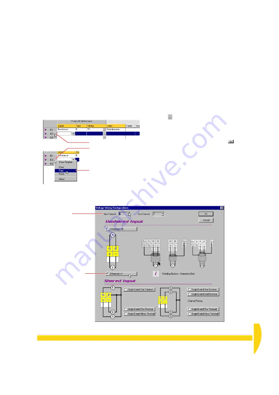
Use copy and paste to duplicate row 2’s
definition into row 3. Then modify row 3 to
instruct the DT800 to read channel 7 as an
unshared differ/– voltage.
To do this…
a) Select all of row
2
by clicking its
row label
(the gray
box containing
R2
b) Now
right
-click the row label of row
2
.
A menu appears (Figure 57).
c) In the right-click menu, choose
Copy
.
All of row 2’s cells are copied to the clipboard.
d) Click the
row label
of row
3
to select the entire row.
e)
Right
-click the row label of row
3
.
f) In the menu that appears, choose
Paste
.
Row 3 and row 2 are now identical.
Notice also the
Clear
command on the right-click
menu. You use this to delete all information from a
selected row.
g) In the
Wiring
column of
R3
, click the Configure
button
.
The Voltage Wiring dialog box opens for row 3
(Figure 58).
h) In the
Start Channel
field at the top of the Voltage
Wiring dialog box, click the up button
until the
field contains
7
.
i) Leave the
Differ/–
configuration selected
and click
OK
.
Channel 7’s channel definition (R3) should look like
Figure 60.
➊
Left-click to select the row
.
➋
Right
-click to reveal the
menu.
➌
Choose
Copy
.
F
IGURE
57
Select R2, copy, and paste into R3
Leave the
Differ/–
option selected.
Set the Start Channel
to
7
.
F
IGURE
58
Defining channel 7 for voltage measurement
Содержание DT800
Страница 1: ...UM 0071 A0 ...
Страница 2: ...UM 0071 A0 ...
Страница 73: ...UM 0071 A0 ...
Страница 74: ...UM 0071 A0 ...


