background image

Prodigy Max Operator’s Manual

29

3.1.1

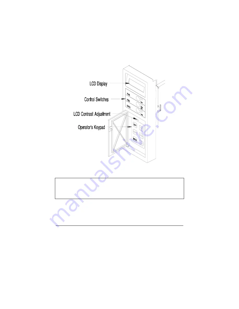
Optional LCD/Keypad Front Panel

The Printer can be equipped with an optional, factory-installed
LCD/Keypad front panel. If this option is installed on your Printer, refer
to this section for menu and function information. 

The front panel is equipped with a 2 row x 16 character LCD display and
a (six) 6 key operator's keypad. The three (3) control switches and
indicators operate the same as indicated in Section 3.1. 

Figure 3-2   Optional LCD/Keypad Front Panel

Note:

If the Printer was purchased with the optional LCD/Keypad
front panel, the configuration for the Printer will be set via the
keypad. On the standard Printer, these configurations are set
through the rear dip switches. 

Содержание Prodigy Plus

Страница 1: ...Prodigy Plus Operator s Manual ...

Страница 2: ... permit any other person or party to duplicate or copy the EPROM s or the information contained in the EPROM s The firmware Software is protected by applicable copyright laws and Licensor retains all rights not expressly granted In no event will Licensor or its suppliers be liable for any damages or loss including direct incidental economic special or consequential damages arising out of the use o...

Страница 3: ...roper power supply cord selection please see below For 230 Volt Operation Europe Use a cord set marked HAR consisting of a min H05VV F cord which has a minimum 0 75 square mm diameter conductors provided with an IEC 320 receptacle and a male plug for the country of installation rated 6A 250V FCC This device complies with Part 15 of FCC rules Note This equipment has been tested and found to comply ...

Страница 4: ......

Страница 5: ...nter from overheating make sure all openings on the Printer are not blocked Do not place the Printer on or near a heat source i e a radiator or heat register Do not use your Printer near water or spill liquid of any kind into it Be certain that your power source matches the rating listed on the back of the Printer If you are unsure check with your dealer or with your local power company Do not pla...

Страница 6: ......

Страница 7: ...tion 13 2 1 Programming Commands 13 2 2 Programming Examples 19 2 3 Configuration and Test Labels 21 2 3 1 Configuration Label 21 2 3 2 Print Test Label 22 2 3 3 Loop back Test Plug 22 Troubleshooting 3 0 Introduction 23 3 1 Controlling Print Quality 24 3 2 Aligning the Printhead 25 3 2 1 Direct Thermal Stock 25 3 2 2 Tag Stock or Stiff Media 25 3 2 3 Mechanical Adjustments 25 3 3 Printhead Alignm...

Страница 8: ...head 38 Appendix A ASCII Control Code Chart A 1 Appendix B Switch Settings and Cable Interfacing B 1 Appendix C Available Fonts and Barcodes C 1 Appendix D Error Codes D 1 Appendix E Cable Listings E 1 Appendix F Specifications F 1 Appendix G Warranty Information G 1 ...

Страница 9: ...ter referred to as the Printer incorporates high performance low cost thermal label printing capabilities The combination of powerful capabilities easy to use features a contemporary look and affordable pricing set a new standard for thermal label printing in retail office and industrial applications ...

Страница 10: ...inter from the plastic bag before use Along with this manual the shipping container s should include the following items Label Printer Printer s front door panel packaged separately Special or additional items purchased 1 2 Supplies Necessary to Print Labels In order for the Printer to generate labels you will need the necessary software and media There are many different types of media and softwa...

Страница 11: ...Parts on your Printer The following illustrations show the major components of your Printer Figure 1 2 is the front panel with the cover open Figure 1 3 is the mechanism detail and Figure 1 4 is the rear view Figure 1 2 Front Panel Front Cover Open ...

Страница 12: ...Getting Started 4 Prodigy Plus Figure 1 3 Mechanism Detail Figure 1 4 Rear View ...

Страница 13: ...r the front door must be installed Complete the following steps when installing the front door 1 Remove the door and Printer from its packaging 2 With the hinges lined up to the proper location on the Printer gently slide the door into the Printer s hinge slots Figure 1 5 Installing the Door ...

Страница 14: ...f description of the buttons light switches and POT are listed in this section Figure 1 6 Switches and Indicators Power Light This light is turned on after the Power Switch on the rear of the Printer is activated Pause Light This light will turn on if any of the following occurs the Pause Button is pressed a print job is canceled with the Stop CancelButton or a fault occurs with the Cutter ...

Страница 15: ...process of being produced and continue on to the next run in the Printer s buffer Feed Button Pressing the Feed Button causes the paper to automatically advance to the first print position of the next label On a new size label multiple labels may be fed before registration occurs Paper Ribbon The Paper Ribbon light is activated when a Light label and or ribbon is not detected Transfer on Switch Th...

Страница 16: ...int Media Installation for Media Loading 1 Slide the Media Retainer to outer end of Media Supply Mount 2 Place the new media supply roll on the Media Supply Mount and slide the Media Retainer firmly back against it Figure 1 7 Media Supply Mount ...

Страница 17: ... the adjusting knob for the movable sensor The gauge behind and below the Printhead can be viewed for making the adjustment If a label is not detected within 12 of feeding the Printer will stop and the Paper Out Indicator will remain lit In this case check the threading of the media around the bottom of the upper and lower media guides If the paper feeds forward only about 1 each time you press th...

Страница 18: ...ted 10 Prodigy Plus 1 7 Media Rewind Instructions 1 Remove the window cover from the front door 2 Fasten the rewind adapter to the front of the Printer as shown in Figure 1 9 Figure 1 9 Attaching the Rewind Adapter ...

Страница 19: ...uting the Media for Rewinding 1 7 1 Peel off Mode 1 If the Peel off Mode is desired route the media backing down past the Rewind Assist Roller see Figure 1 10 to the media rewinder and reverse the serrated tear off plate Note Do not install the rewind adapter when using the Peel off Mode Caution Using the Peel off Mode without the Present Sensor installed and enabled can cause labels to become jam...

Страница 20: ...ead Lift Lever clockwise to the up position 2 Slide the Ribbon onto the Ribbon Supply Hub Route the ribbon see Figure 1 11 and attach the ribbon to the Ribbon Take up Hub 3 Engage the Printhead by rotating the Head Lift Lever counterclockwise to the down position Figure 1 11 Ribbon Loading 4 Ensure that the Transfer Switch is in the on position Note If using a ribbon that is translucent i e color ...

Страница 21: ...mands In order to be ready for a command sequence the Printer must first receive a special character called an attention getter that informs the Printer that it is about to receive a command and the type of command it will be Immediate Commands System Level Commands and Font Loading Commands each have their own attention getter The attention getter character is followed by a command character that...

Страница 22: ...ypes must be in this sequence 1 Attention Getter 2 Command Character 3 Parameters that must be entered by the user if any Command Character Must Enter Parameters Printer Responds Command N Y Reset A N Y Send ASCII status string B N N Toggle pause C N N Cancel D N N SOH shutdown E N Y Send batch quantity F N Y Send status byte Table 2 2 Immediate Commands ...

Страница 23: ...f paper to feed per label d Set Printer to double buffer mode Used to print a label while a second is formatting in memory E Set quantity for stored label Ennnn Set Quantity for stored label e Select edge sensor Used for see through media sensing F Form feed Feeds one label at a time f Set form stop position Backfeed Set distance to peel tear off position fnnn 3 digits from sensor G Print last lab...

Страница 24: ...x x C 0 2 8 ips s Set up for one print buffer T Printhead dot pattern test label t Test RAM memory module Must be in Test Mode a bbbK Module Good A 1 top slot B 2 bottom slot bbb 256 or 512 for size of module U Label format field replacement V Software switch settings Vn n 4 Label Present 2 color ribbon 1 Cutter Enable v Firmware version information Sends version string to Host W Request memory mo...

Страница 25: ... 2 or 3 0 005 steps Default is D22 E Terminate label format and print label G Place data in global register H Enter heat setting The amount of heat applied per dot row can be used to help control print quality Hnn nn 2 digits 1 20 10 is nominal and default m Set metric mode The Printer must be reset in order to return to standard measure P Print speed Px x C O 2 to 8 ips p Set label backup speed p...

Страница 26: ...dded to field Make last field entered decrement alphanumeric pii Make last entered field decrementing 0 Z p Zero fill character ii Data subtracted from field Set count by amount nn Set count by amount nn 2 digits Skip of labels before updating count fields and time fields Table 2 4 Label Formatting Commands Continued There are two special commands used by the Printer the STX S Recall Global Data a...

Страница 27: ... 6 CC P PR Description c D N N Assign Font ID Number ID Number 100 to 999 s W Y N Font Descriptor c E N N Character Code ASCII Value of Character s W Y N Character Download Data Bytes of Bit mapped Data Table 2 6 Font Loading Commands CC Command Character P Must Supply Parameters Y N PR Printer Responds Y N 2 2 Programming Examples STX L CR H07 CR D11 CR 19110080100002510K OHM 1 4 WATT CR 1a621000...

Страница 28: ...bar codes shown in Appendix B by altering the example s fields Refer to Figures 2 2 and 2 3 for a brief explanation of the data fields that appear in the barcode shown below STX L CR D11 CR 1A93040001501000123456789 CR 121100000000100Barcode A CR E STX L STX L on line 1 is used to enter the label formatting mode Figure 2 2 Example line 3 Figure 2 3 Example line 4 ...

Страница 29: ...rtant information To print a Configuration and Test Label follow the outlined steps 1 Hold in the Feed Button and turn on the Printer until the Printer feeds one label 2 After the Printer feeds one label release the Feed Button after a brief hesitation the Configuration and Test Label will print THU MARCH 17 1997 12 25 077 VER BA 03 02 04 08 97 SYSTEM ROM CHECKSUM 8F7B IS GOOD FONT ROM CHECKSUM 2E...

Страница 30: ...mining bad Printheads or rollers Figure 2 5 Print Test Label 2 3 3 Loop back Test Plug A Loop Back Test Plug can be installed for serial communications testing Below are examples of the Loop Back Test Plugs If the Test Plug is installed the following two lines will be added to the Configuration Label SERIAL LOOP BACK CHECK GOOD CTS DTR LOOP BACK CHECK IS GOOD Figure 2 6 Loop Back Test Plugs ...

Страница 31: ...ty when using media other than the recommended 4 mil stock It also provides basic ideas to help identify common installation and communication interfacing problems If there is any doubt about your ability to perform the procedures outlined in this chapter contact a qualified service technician before making any adjustments ...

Страница 32: ...example low cost direct thermal stocks have high reaction temperatures therefore it takes a great deal of heat to make clear images on this type of paper The Printer has two ways to compensate for this first set the burn time to a higher value by using the H Label Formatting Command This causes more heat to be transferred into the media and consequently generates a darker image second adjust the P...

Страница 33: ...ermal stock the Printhead burn line needs to be further back on the roller where there is more contact with the roller This causes heat to transfer to the paper more efficiently 3 2 2 Tag Stock or Stiff Media The Printer is adjusted at the factory using 5 mil thick label stock If heavier tag stock is used the Printhead may need to be adjusted forward 3 2 3 Mechanical Adjustments The Printhead is p...

Страница 34: ...s Figure 3 1 Components for Printhead alignment Print rotated bars and inspect the quality With a 1 16 hex key turn the left and right head adjust screws counter clockwise 1 4 to 1 2 turn until the desired print quality is achieved ...

Страница 35: ...f even a 1 4 turn will cause a big difference in print quality Caution Do not turn the head adjustment screws more than 2 complete turns in either direction Damage to the Head Mount Assembly will result if the adjustment screws are turned too far The alignment procedure and the sequence that should be followed is described in section 3 2 1 This procedure should correct poor print quality however a...

Страница 36: ... stock feeds straight use a full roll of 4 102 mm or 4 25 108 mm wide stock and complete the following steps 1 Rotate the Media Guide down and install the stock keep the Media Guide in the down position 2 Press the feed button to feed the labels until the stock begins to track at a stable position 3 Rotate the Media Guide to the up position and slide the Media Guide in or out until the inside edge...

Страница 37: ...he Printhead assembly If rippling or bagging occurs follow the procedures outlined in steps 2 through 6 2 To adjust the Ribbon Shield see Figure 3 2 temporarily move the ribbon and loosen the screw located on the left end of the Head Support Plate do not remove the screw This end of the shield can be adjusted up or down in order to even out the ribbon tension across the full width of the ribbon No...

Страница 38: ...ven across the entire width of the ribbon 5 Feed three or four labels and observe the ribbon as it travels from the Ribbon Supply Hub 6 Feed the ribbon and paper out the front of the Printer together and check the ribbon for drifting If the ribbon overlaps one edge of the paper stock the ribbon and paper are not following the same path In this case the paper tracking may need to be re adjusted If ...

Страница 39: ...es adjustment if media widths of 3 5 89 mm or less are used To make this adjustment loosen the two mount screws that fasten the Head to the Support Plate leaving the screw on the left slightly snug Load the media and engage the Printhead by rotating the Head Lift Lever to the down position Turn the adjustment screw clockwise until the support plate moves down and contacts the bearing plate underne...

Страница 40: ...nd some of these tips helpful After the corrective action is taken press the feed button to clear the alarm Contact a qualified service technician for problems that persist or are not covered in this section Unacceptable print quality The Printhead may be dirty clean the Printhead see Section 4 1 The Printhead temperature is too high Use the software control to adjust the burn time and or heat set...

Страница 41: ...n again The Printer is set for 8 data bits but the transmitting device is set for 7 data bits or vice versa Check the current data bits setting switch 4 on the back of the Printer The ribbon does not advance The ribbon is installed incorrectly Make sure that the dull side side with ink is facing the paper A bad ribbon paper combination is resulting in an insufficient amount of friction between pap...

Страница 42: ...stock The Printhead is not properly aligned call for service Printer fails to turn on A fuse may be blown call for service Faulty AC cord A bad power switch may exist on the Printer call for service A faulty AC wall outlet Label advances 1 2 inches before a fault indication The ribbon is installed incorrectly Make sure that the dull side side with ink is facing the paper A bad ribbon paper combina...

Страница 43: ... Plus 35 Label advances 12 inches before a fault indication A hardware problem may exist call for service The Media Sensor may be out of adjustment The Media Sensor or Media Sensor Circuitry may be defective call for service ...

Страница 44: ...Troubleshooting 36 Prodigy Plus ...

Страница 45: ...sive cleansers or solvents Drive Roller Print quality may be affected if the drive roller becomes contaminated with grit label adhesive or ink To clean the Drive Roller complete the following steps 1 Remove the Tear off Plate see Figure 1 3 2 Turn the Head Lift Lever to raise the Printhead to the up position 3 Dampen a clean soft cloth with Isopropyl Alcohol and wipe off any debris from the Drive ...

Страница 46: ...abels that contain spots or light streaks Once you notice these signs follow the steps below to clean the Printhead 1 Turn off the power and unplug the Printer 2 Raise the cover and turn the Head Lift Lever to the up position 3 Dampen a cotton swab with isopropyl alcohol and insert into the Printhead as shown below Gently rub the underside of the Printhead with the moistened swab Figure 4 2 Cleani...

Страница 47: ... 75 4B k 107 6B FF 12 0C 44 2C L 76 4C l 108 6C CR 13 0D 45 2D M 77 4D m 109 6D SO 14 0E 46 2E N 78 4E n 110 6E SI 15 0F 47 2F O 79 4F o 111 6F DLE 16 10 0 48 30 P 80 50 p 112 70 DC1 17 11 1 49 31 Q 81 51 q 113 71 DC2 18 12 2 50 32 R 82 52 r 114 72 DC3 19 13 3 51 33 S 83 53 s 115 73 DC4 20 14 4 52 34 T 84 54 t 116 74 NAK 21 15 5 53 35 U 85 55 u 117 75 SYN 22 16 6 54 36 V 86 56 v 118 76 ETB 23 17 7...

Страница 48: ... 8B 1 2 171 AB 203 CB Ù 235 EB î 140 8C 1 4 172 AC 204 CC ý 236 EC ì 141 8D 173 AD 205 CD Ý 237 ED Ä 142 8E 174 AE 206 CE 238 EE Å 143 8F 175 AF 207 CF 239 EF É 144 90 176 B0 ð 208 D0 240 F0 æ 145 91 177 B1 Ð 209 D1 241 F1 Æ 146 92 178 B2 Ê 210 D2 242 F2 ô 147 93 179 B3 Ë 211 D3 3 4 243 F3 ö 148 94 180 B4 È 212 D4 244 F4 ò 149 95 Á 181 B5 213 D5 245 F5 û 150 96 Â 182 B6 Í 214 D6 246 F6 ù 151 97 À ...

Страница 49: ...off off on SW 3 off on off on off on on Table B 1 Baud Rate SW 4 Data Bits Parity Stop Bits on 7 None 2 off 8 None 1 Table B 2 Word Length SW 5 Prodigy Compatible On Prodigy Off Prodigy Plus SW 6 Present Sensor On Enabled Off Disabled SW 7 Ribbon Sensor On Color translucent Off Black opaque SW 8 Cutter On Cutter Enabled Off Cutter Disabled Table B 3 Options ...

Страница 50: ...o operate properly Signal Pin TX 2 RX 3 BUSY 20 Ground 7 Jumper 4 to 5 Shield 1 Table B 1 I O Port Wiring When the Printer is turned on it will default to pre determined interfacing parameters The default values are in Table B 2 Parameter Default Value BAUD 9600 Data Bits 8 Parity None Stop Bits 1 Table B 2 Printer Default Communication Parameters Altering the switch positions of Dip Switch S1 on ...

Страница 51: ...ting command z These fonts are non proportional monospaced fonts all of the characters take up the same amount of space when printed The Triumvirate font number 9 is a proportional font each character will take up a different amount of space when printed Font Valid ASCII Characters 0 32 127 1 32 168 171 172 225 2 32 168 171 172 225 3 32 35 38 40 58 65 90 128 142 144 146 153 154 156 157 165 168 225...

Страница 52: ...indicate the number of dots FONT HEIGHT WIDTH SPACING Font 0 7 5 1 Font 1 13 7 2 Font 2 18 10 2 Font 3 27 14 2 Font 4 36 18 3 Font 5 52 18 3 Font 6 64 32 4 Font 7 32 15 5 Font 8 28 15 5 Table C 2 Font Sizes Font 0 96 character alphanumeric upper and lower case Prodigy Plus Prodigy Plus 152 ...

Страница 53: ...rcodes Prodigy Plus C 3 Font 1 145 character upper and lower case alphanumeric with descenders and ascenders Prodigy Plus Prodigy Plus 152 Font 2 138 character alphanumeric upper and lower case Prodigy Plus Prodigy Plus 152 ...

Страница 54: ...Available Fonts and Barcodes C 4 Prodigy Plus Font 3 62 character alphanumeric uppercase Prodigy Plus Prodigy Plus 152 Font 4 62 character alphanumeric uppercase Prodigy Plus ...

Страница 55: ...Available Fonts and Barcodes Prodigy Plus C 5 Prodigy Plus 152 Font 4 continued ...

Страница 56: ...Available Fonts and Barcodes C 6 Prodigy Plus Font 5 62 character alphanumeric uppercase Prodigy Plus Prodigy Plus 152 ...

Страница 57: ...Available Fonts and Barcodes Prodigy Plus C 7 Font 6 62 character alphanumeric uppercase Prodigy Plus ...

Страница 58: ...Available Fonts and Barcodes C 8 Prodigy Plus Prodigy Plus 152 Font 6 continued ...

Страница 59: ...Available Fonts and Barcodes Prodigy Plus C 9 Font 7 OCR A size I Prodigy Plus Prodigy Plus 152 Font 8 OCR B size III Prodigy Plus Prodigy Plus 152 ...

Страница 60: ...Available Fonts and Barcodes C 10 Prodigy Plus Font 9 Identifies the internal Triumvirate font Point sizes are selected by number in the bar code height Prodigy Plus ...

Страница 61: ...Available Fonts and Barcodes Prodigy Plus C 11 Prodigy Plus 152 Font 9 continued ...

Страница 62: ...43 45 57 65 90 2 1 3 1 I Varies No 36 43 45 58 65 68 2 1 3 1 J Varies M 10 48 57 Numeric only 2 1 3 1 K Up to 14 M 10 48 57 Numeric only Option is Last Character for Second M 11 Checksum 2 1 3 1 L 13 M 10 48 57 Numeric only 2 1 3 1 M 2 Yes 48 57 Numeric only N A N 5 Yes 48 57 Numeric only N A O Varies No 0 127 ASCII characters N A p Varies Yes 48 57 Numeric only Same as fonts Q 19 Yes 48 57 Numeri...

Страница 63: ... Fonts and Barcodes Prodigy Plus C 13 Barcode A Code 3 of 9 Barcode B UPC A Barcode C UPC E Barcode D Interleaved 2 of 5 Barcode E Code 128 Barcode F EAN 13 Barcode G EAN 8 Barcode H Health Industry Barcode HBIC ...

Страница 64: ...de I Codabar Barcode J Interleaved 2 of 5 w module 10 checksum Barcode K Plessey Barcode L Interleaved 2 of 5 w module 10 checksum and shipping bearer bars Barcode M 2 Digit UPC addendum Barcode N 5 Digit UPC addendum Barcode O Code 93 Barcode p Postnet ...

Страница 65: ...Available Fonts and Barcodes Prodigy Plus C 15 Barcode Q UCC EAN Code 128 Barcode R UCC EAN Code 128 KMART NON EDI Bar Code z PDF 417 Prodigy Plus 203DPI only ...

Страница 66: ......

Страница 67: ...The Printer did not understand the command sequence and therefore terminated the command interpreter Uppercase R This code is sent every time the Printer is turned on It signals that there was a hardware reset Uppercase T This code signals that there was a software reset A software reset results from sending the SOH command sequence to the Printer or by doing a front panel reset BELL HEX 07 This i...

Страница 68: ...D 2 Prodigy Plus ...

Страница 69: ...inter to PC 9 Pin DB9S RS 232 556002 Printer to PC 25 Pin DB25S RS 232 899516 Printer to PC Parallel Port DB25P Table E 1 Printer Interface Cables Pin Description 1 CHASSIS 2 TXD RS 232 3 RXD RS 232 4 RTS 4 7k ohm to 5VDC 5 CTS input 7 LOGIC GROUND 14 5 VDC 100 mA maximum 20 BUSY output Table E 2 Printer Pin Connections ...

Страница 70: ...e E 1 Null Modem Cable MXM Note Cable is used for typical connection to other DCE equipment with Xon Xoff flow control STRAIGHT CABLE MM Figure E 2 Straight Cable MM Note Cable is used for typical connection to other DCE equipment with Xon Xoff flow control ...

Страница 71: ...le is used for connection to a PC compatible with DB25P communication ports Flow control is either Xon Xoff or CTS DTR PC DB9P TO PRODIGY PLUS Figure E 4 PC DB9P to Printer Note Cable is used for connection to a PC compatible with DB9P communication ports Flow control is either Xon Xoff or CTS DTR ...

Страница 72: ...er is a one way communication self powered device No external power source is required The adapter has a sophisticated microprocessor built into the head assembly that converts standard Centronics parallel to RS 232 serial communication This cable is useful when using the Printer with a PC that has only a parallel Printer port available Figure E 5 Centronics Parallel Interface Converter Cable is u...

Страница 73: ...rientation Maximum Print Width 4 1 W 104mm 203 dpi Maximum Print Length 5 25 133mm with standard RAM up to 20 25 514mm with optional 512K Memory Module White Space Slew Rate 2 0 8 0 51mm 203 mm per second Maximum Fields Per 200 5K data per label maximum Label Minimum Dot Size Prodigy Plus 0 005 0 127 mm square Prodigy Plus 152 0065 165mm square Optional Dot Sizes Prodigy Plus 0 010 0 25mm 0 015 0 ...

Страница 74: ...cpi font 0 at 1X 70 cpi font at 6 at 8X Prodigy Plus 152 25 64 cpi font 0 at 1X 54 cpi font at 6 at 8X Barcodes Code 39 Interleaved 2 of 5 Code 128 Codabar LOGMARS UPC A and UPC E EAN 8 and EAN 13 MSI Plessey Universal Shipping Container Symbology Code 39 variations to produce all industry standards i e HIBC AIAG PDF 417 203 DPI only Postnet and UCC EAN 128 and PDF 417 Barcode Density Prodigy Plus...

Страница 75: ...ly roll Label Material Thermal transfer plain coated papers vinyl Mylar metalized paper nonwoven fabric fine woven fabric thermal visible light scalable paper infrared scalable paper thermal ticket tag stock thermally sensitive plastic stock Thermal Transfer Ribbons Black or colored inks 1182 360 meters long 4 6 microns thick back coated 10 label width 1 inch cores no notch required Media Sensing ...

Страница 76: ...9 0 100 D Label length 99 99 0 500 E Backing thickness 0 005 0 0023 F Label thickness 0 005 0 0023 G Width of sensor opening 0 500 0 200 H Distance from edge of Media to edge of sensor opening 2 250 0 200 I Reflective sensor mark width 4 00 1 000 K Reflective sensor mark length 99 99 0 100 J Distance between reflective mark 99 99 0 500 Units of measure are in inches Table F 1 Media Dimensions ...

Страница 77: ...mal Transfer Rear communications DIP switch SW I and darkness potentiometer Communications Interfacing Communications IEEE RS 232C IRS 422 at 300 600 1200 2400 4800 or 9600 baud Character Set ANSI ASCII character set Word Length Selectable 7 bit or 8 bit data format Handshaking XOn XOff in receive mode only and CTS DTR Input Buffer Approximately 7000 bytes Xon XOff is transmitted and DTR goes low ...

Страница 78: ...r at 1 2A Grounding Unit must be connected to a properly grounded receptacle Environmental Operating Temperature 40 F to 90 F 4 C to 32 C Humidity 10 to 95 non condensing Ventilation Free air movement Dust Non conducting non corrosive Electromagnetic Radiation Moderate RF fields can be tolerated Physical Dimensions 10 H x 10 W x 18 D 254mm H x 254mm W x 457 mm D Weight 36 lbs 16 33 kg ...

Страница 79: ...t Sensor This option will not allow the next label to be printed until the last label is removed from the Printer 256K RAM Fonts can be loaded into the RAM module Memory Module by most programs that are capable of transmitting fonts in HP PCL4 format 512 RAM Same as the 256K module except when the Memory Module 512K module is in slot A the dot memory printable length is doubled 256K and 512K Flash...

Страница 80: ...re for IBM PC or compatible Twinax Coax This device supports printing from IBM and IBM compatible computers On Line Verification Used to guarantee barcode quality and compliance Kanji A Japanese font that supports the full 24x24 and 16x16 dot gothic style Kanji characters ...

Страница 81: ... manufactured This warranty also does not cover loss damages resulting from accident or damages resulting from unauthorized service Thermal Printhead This warranty is limited to a period of 365 days or 1 000 000 linear inches of use whichever comes first for the Prodigy Plus and Prodigy Plus 152 thermal Printhead This 365 day warranty is valid only if a Datamax approved thermal or thermal transfer...

Страница 82: ...amax shall be subject to Datamax s confirmation that such product meets Datamax warranty In the event of a defect covered by its warranty Datamax will return the repaired or replaced product to the Purchaser at Datamax s cost With respect to a defect in Hardware covered by the warranty the warranty shall continue in effect until the end of the original warranty period or for sixty 60 days after th...

Страница 83: ...der shall in no event exceed the total amounts paid to Datamax hereunder by the purchaser for a defective product In no event shall Datamax be liable to the purchaser for any damages resulting from or related to any failure or delay of Datamax in the delivery or installation of the computer hardware supplies or software or in the performance of any services Some States do not permit the exclusion ...

Страница 84: ...Warranty Information G 4 Prodigy Plus ...

Страница 85: ...Prodigy Max Operator s Manual ...

Страница 86: ...t to authorize or permit any other person or party to duplicate or copy the EPROM s or the information contained in the EPROM s The firmware Software is protected by applicable copyright laws and Licensor retains all rights not expressly granted In no event will Licensor or its suppliers be liable for any damages or loss including direct incidental economic special or consequential damages arising...

Страница 87: ...For 230 Volt Operation Europe Use a cord set marked HAR consisting of a min H05VV F cord which has a minimum 0 75 square mm diameter conductors provided with an IEC 320 receptacle and a male plug for the country of installation rated 6A 250V FCC This device complies with Part 15 of FCC rules Note This equipment has been tested and found to comply with the limits for a Class A digital device pursua...

Страница 88: ...solid surface To protect your printer from overheating make sure all openings on the printer are not blocked Do not place the printer on or near a heat source Do not use your printer near water or spill liquid into it Be certain that your power source matches the rating listed on your printer If you are unsure check with your dealer or with your local power company Do not place the power cord wher...

Страница 89: ... 10 2 3 1 Interfacing to the Printer 11 2 3 2 Dip Switch Settings 13 2 4 Memory Cartridges 14 2 5 Media Loading 15 2 5 1 Using the Optional Internal Rewind 18 2 5 2 Using the Peel and Present Option 20 2 6 Ribbon Installation and Removal 22 Using Your Printer 3 0 Introduction 25 3 1 Front Control Panel 25 3 1 1 Optional LCD Keypad Front Panel 27 3 2 Using the Optional LCD Keypad Front Panel 28 3 3...

Страница 90: ...nce and Adjustments 5 0 Introduction 51 5 1 Printer Maintenance Schedules 51 5 1 1 Cleaning the Printhead 52 5 2 Troubleshooting 53 5 2 1 Optional LCD Keypad Front Panel Alarms 55 5 3 Mechanical Adjustments 56 5 3 1 Media Width Adjustment 57 5 3 2 Media Sensor Adjustment 58 5 3 3 Printhead Replacement 59 Appendix s Appendix A ASCII Control Chart A 1 Appendix B Available Fonts and Barcodes B 1 Appe...

Страница 91: ...th its standard 203 DPI Dots Per Inch printhead the Printer can print labels at speeds of up to 10 per second The thermal transfer model allows for the use of thermal transfer ribbons An innovative dot history control circuit called SEAQ Sequential Energy Adjustment for Quality provides exceptional print quality by monitoring the printhead data and automatically adjusting the printhead element tem...

Страница 92: ...ii Prodigy Max Operator s Manual Figure 1 1 Overall View ...

Страница 93: ...with operator and field installed options such as a Cutter Peel and Present requires factory installed Internal Rewind On line Verification DRAM Internal Batch Cartridge and Memory Cartridges In addition the Printer can be purchased with factory installed options i e Internal Rewind Ribbon Saver 300 DPI printhead and LCD Keypad front panel that expand the Printer s capabilities Figures 1 1 and 1 2...

Страница 94: ...inimum in batch mode 75 minimum in tear off or peel mode 12 300 DPI w 1MB standard 25 minimum in batch mode 75 minimum in tear off or peel mode Media Type Roll Fed Die Cut Continuous Fan Fold Tags or Tickets Media Thickness 0025 0 010 0635mm to 254mm standard widths 0050 0080 for 75 1 label widths Media Supply 8 203mm maximum diameter on 3 76mm cores Bar Codes Code 39 Interleaved 2 of 5 Code 128 S...

Страница 95: ...d Front panel with a 2 row x 16 character LCD display and a 6 key operator s keypad Ribbon Saver Eliminates ribbon waste when feeding past non printing areas DRAM Expandable to 4MB via a daughter board 256KB 512KB Permanent Storage of Custom Fonts Graphics and Flash Cartridge Formats Cutter with Tray Maximum Thickness 0 010 254mm Internal Rewinder 5 maximum O D capacity with no core Twinax Coax Su...

Страница 96: ... 00 50 8 mm 2 50 64 0 mm 3 00 76 2 mm 3 00 76 2 mm 3 00 76 2 mm 3 50 89 0 mm 4 00 101 6 mm 4 00 101 6 mm 4 25 108 0 mm 4 25 108 0 mm 4 25 108 0 mm 4 50 114 3 mm 4 50 114 3 mm 4 50 114 3 mm The standard ribbon length is 1478 450m It is recommended that the width of the thermal transfer ribbon be within 10 of the label width Additional sizes other than those listed above are available on a custom or...

Страница 97: ... 0 0025 G Width of sensor opening 0 500 0 200 H Distance media edge to sensor opening 2 250 0 200 I Reflective sensor mark width It is recommended that the entire width of the label is marked 4 00 1 000 J Distance between reflective mark 99 99 0 500 K Reflective sensor mark length 99 99 0 100 Table 1 1 Media Specifications Note The reflective sensor mark must be carbon based The sensor is infrared...

Страница 98: ...iner s for signs of shipment damage If damage is evident contact the carrier directly to specify the nature and extent of the damage The printer is packed in molded styrofoam packaging The Printer is enclosed in a plastic bag to reduce the chance of moisture damage during shipment Remove the Printer from the plastic bag In addition to this manual the shipping container s should include the followi...

Страница 99: ...Printer is also manufactured for 230 VAC operation most of these Printers are shipped to international markets If you are uncertain as to the power requirements of the Printer or the outlet you are connecting to check with a qualified service technician to verify the installation before connecting AC power CAUTION Check the rear AC switch settings before applying power The facing arrows must by se...

Страница 100: ... changed If you wish to change from 115 VAC to 230 VAC follow the instructions outlined below 1 Remove the AC power cord if installed 2 Insert a flat bladed screwdriver into the release slot and push out the fuse holder voltage selector switch 3 Flip rotate the fuse holder voltage selection switch over and re insert it 4 Attach the 230V power cord Figure 2 1 Selecting 230 VAC ...

Страница 101: ...ter s cables as outlined below 1 Make sure both the Printer and host computer are turned off 2 Plug the serial cable connector securely into the Printer s serial connector and then attach it to the connector 3 Plug the other end of the cable into the computer s serial interface Note An optional parallel port is available See your retailer for details Figure 2 2 Rear Printer Connections ...

Страница 102: ...abeled serial and is located on the back of the Printer Several typical cable interfaces are listed in Table 2 1 The Printer supports both XON XOFF and CTS DTR handshaking For connection to most host systems the XON XOFF handshaking works to reduce the number of wires needed in the interface cable For interfacing RS 422 devices the XON XOFF handshake is the only appropriate method Refer to Table 2...

Страница 103: ...s are shown below Contact your reseller for part numbers and ordering information Null Modem MXM PC DB25P to Printer PC DB9P to Printer RS 422 Connection Table 2 1 Interface Cable Applications Other applications may require a parallel connection from the Printer to the host The Printer can be connected to the host with a standard parallel printer cable if the Printer is equipped with the optional ...

Страница 104: ...OFF OFF OFF ON ON ON ON OFF OFF ON ON OFF OFF ON ON OFF ON OFF ON OFF ON OFF ON X X X X X X X X X X X X X X X X X X X X X X X X X X X X X X X X X X X X X X X X Word length Parity 7 Bit Even 8 Bit None X X X X X X ON OFF X X X X X X X X Compatibility Mode Form Edge Offset Offset 1 10 27 9mm Offset 2 20 55 9mm X X X X X X X X OFF ON X X X X X X Present Sensor Enable Disable X X X X X X X X X X ON OF...

Страница 105: ...r internal batch Follow the instructions outlined below when installing memory cartridges 1 Ensure that all printing has been completed 2 Open the Side Access Cover 3 Plug the Memory Cartridge into the Memory Cartridge Slot with the label face up Figure 2 3 Installation of a Memory Cartridge Note Use only memory cartridges designed specifically for your Printer flash modules have a Write Protect S...

Страница 106: ...3 1 before loading media Follow the instructions outlined below when installing the media stock 1 Open the Printer s Side Access Cover 2 Rotate the Printhead Latch 1 counterclockwise to unlatch and raise the Printhead to an upright position 3 Lower the Hinge Plate 2 4 Slide the Media Edge Guide 3 to the outer edge and rotate it to the down position Figure 2 4 Media Access ...

Страница 107: ...fanfold media as shown in figure 2 5b 5 Place the Media Supply Roll on the Media Hub Assembly Slide the media retainer against the supply roll and tighten the thumb screw Figure 2 5a Media Installation Note Do not use the media retainer if the Media Supply Roll is wider than 4 inches 102mm ...

Страница 108: ...n in Figure 2 5b 7 Rotate the Media Edge Guide up and slide it to the media s edge 8 Close the Hinge Plate and lower the Printhead by rotating the Printhead Latch clockwise to the latched position Figure 2 5b Media Installation Note If the media is not sensing try adjusting the Media Edge Sensor by turning the Media Edge Sensor Adjustment knob see Section 5 3 2 ...

Страница 109: ...below Note The Arc Plate is supplied only with the Internal Rewind Option 1 Turn off the Printer and open the Side Access Cover 2 Follow steps 2 3 and 4 of Section 2 5 before installing media 3 Open the Lower Right Front Panel 4 Remove the Arc Plate from its stored position and install it on the front of the Printer as shown in Figure 2 6 Figure 2 6 Installing the Arc Plate for Internal rewind ...

Страница 110: ...tween the Media Sensor and over the Platen Roller located beneath the Printhead around the Arc Plate and to the Media Rewinder as shown Figure 2 7 7 Place the Clasp over the end of the media and rotate the Media Rewinder a few turns 8 Rotate the Media Edge Guide up and slide it to the media s edge 9 Close the Hinge Plate and latch the Printhead by rotating the Printhead Latch upward to the latched...

Страница 111: ...tions outlined below 1 Turn off the Printer and open the Side Access Cover 2 Follow steps 2 3 and 4 of Section 2 5 before installing media 3 Open the Lower Front Panel 4 Using a phillips screw driver remove the Tear Bar invert it flip it over and re install it as shown in Figure 2 8 Figure 2 8 Using the Peel and Present Option Note If media narrower than 4 inches is used refer to Section 5 3 1 bef...

Страница 112: ...oute the media liner backing around the Tear Bar to the Media Rewinder as shown in Figure 2 9 8 Place the Clasp over the end of the media and rotate the Media Rewinder a few turns 9 Rotate the Media Edge Guide up and slide it to the media s edge 10 Lift and snap the Lower Right Front Panel closed 11 Close the Hinge Plate and latch the Printhead by rotating the Printhead Latch clockwise to the latc...

Страница 113: ...ow the instructions below when installing the thermal transfer ribbon Ribbon Installation 1 Open the Side Access Cover 2 Rotate the Printhead latch counterclockwise to unlatch and raise the Printhead 3 Lower the Hinge Plate 4 Place the new Ribbon Supply Roll on the Supply Hub making sure that the ribbon roll is pushed up against the hub flange Figure 2 10 Ribbon Installation ...

Страница 114: ...clockwise to unlatch it 7 Raise the J hook upward and place the end of the ribbon over the Take Up Hub Figure 2 11 Ribbon Installation showing J hook 8 Slide the J hook back into place as shown in Figure 2 11 While holding the ribbon Take Up Hub rotate the J hook counter clockwise to latch 9 Turn the Take Up Hub until all of the ribbon slack is removed ...

Страница 115: ...Front Panel Option see Section 3 2 Figure 2 12 Selecting Ribbon On Thermal Transfer Ribbon Removal 1 Cut the ribbon anywhere between the Take Up Hub and Printhead 2 Rotate the Printhead Latch counterclockwise to raise the Printhead then lower the hinge plate 3 While holding the ribbon Take Up Hub rotate the J hook clockwise to unlatch it then slide off the used ribbon 4 Turn the Ribbon Supply Hub ...

Страница 116: ... explain the front panel operation how to install memory cartridges and replace the fuse 3 1 Front Control Panel The Printer has five 5 operator accessible switches and three 3 LED indicators see Figure 3 1 A brief description of the switches and LED indicators is listed in this section ...

Страница 117: ...Prodigy Max Operator s Manual 27 Figure 3 1 Front Panel ...

Страница 118: ...rinting to resume and extinguishes the LED When pressed the paper will advance to the first print position of the next label In addition this button is used to clear fault conditions indicated by the Ribbon Media LED Interrupts and deletes the active print job RIBBON ON OFF SWITCH For direct thermal printing no ribbon slide the switch to the off position For thermal transfer printing ribbon instal...

Страница 119: ...on The front panel is equipped with a 2 row x 16 character LCD display and a six 6 key operator s keypad The three 3 control switches and indicators operate the same as indicated in Section 3 1 Figure 3 2 Optional LCD Keypad Front Panel Note If the Printer was purchased with the optional LCD Keypad front panel the configuration for the Printer will be set via the keypad On the standard Printer the...

Страница 120: ...to move to the primary Basic Function menu then use the Õ Ö arrow keys to scroll to the desired sub menu Once in the desired sub menu use the Ø arrow keys to move into or out of the desired sub menu Use the Õ Ö arrow keys to display the available values Use the enter key to set the desired value or condition When the enter key is pressed an asterisk will appear indicating that the selection has be...

Страница 121: ... the parameters for the communication port PORTA 9600 8 N 1 BOTH Communications port and Baud rate Word length Parity Stop Bits Protocol Word lengths 7 8 Parity None Even Odd Stop Bits 1 2 Protocols BOTH DTR XON XOFF Baud rates 300 600 1200 2400 4800 9600 19200 BASIC FUNCTION LABEL PRESET Selects the Peel and Present Option ENABLE DISABLE Selects the Present Sensor No Present Sensor selected BASIC...

Страница 122: ...etup ADVANCED SETUP COUNTERS ABSOLUTE VALS RESETTABLE VALS RESET COUNTERS Non resettable counter viewed only User resettable counter can keep track of labels Resettable values re start at 0 ADVANCED SETUP DATE TIME Allows current date and time to be set SET DAY NAME day hh mm a dd mon yr ADVANCED SETUP LABEL OPTIONS HEAT SETTING Values 00 to 30 10 0 lightest 30 darkest PRINT SPEED Values 2ips to 1...

Страница 123: ...Allows the user to change the entry password Internal Module ID A Memory size 4K byte blocks default 15 Scalable font cache allocation 4K byte blocks 0 Scalable font symbol set selection see Programmer s Manual ADVANCED SETUP OPERATION PAUSE MODE ENABLE DISABLE FEEDBACK MODE ENABLE DISABLE TEST MODE ENABLE DISABLE Suspends printing between each label until the pause button is pressed Returns ASCII...

Страница 124: ...l and analog sensors Displays digital sensors with active values below them HD Head CT cutter LP label present RS ribbon saver D Down D Down Y Blocked D Down U Up U Up N Not Blocked U Up ANALOG SENSORS Displays 4 analog sensors with sensor values below each THR Thermal RF reflective TOF mode RIB Ribbon motion TR Transmissive only the active mode is displayed SERIAL LOOPBACK SERIAL PORTA Serial loo...

Страница 125: ...tionally install one of the Self Test Plugs Press and hold the feedbutton and turn the Printer on Release the Feed switch after the Ribbon Media LED indicator flashes once The Printer will then print the two test labels and operation will continue in the Character Dump Mode Figure 3 3 Self Test Plugs Note After performing a Power Up and Self Test the Printer will be in Character Dump Mode Turn the...

Страница 126: ... on a standard printer without the test plugs installed FRI SEPTEMBER 23 1996 10 12 340 VER GA 1 14 01 30 96 ROM CHECKSUMS U13 47 2091 01P U24 47 2090 01P U34 47 2088 01B U2 47 2089 01B SYSTEM RAM CHECKS_ _ _ _ GOOD SYSTEM RAM SIZE_ _ 512 KBYTES SERIAL PORT BAUD RATE IS 9600 TRANSFER SWITCH IS ON SWITCH 1 1 2 3 4 5 6 7 8 ON ON ON OFF OFF OFF OFF OFF INTERNAL 1 2 3 4 5 6 OFF OFF OFF OFF OFF OFF INP...

Страница 127: ...d to determine whether the Printhead is in need of replacement Good and Bad test pattern labels are shown in Figure 3 5 Good test label indicates Printhead is operating normally Streaks in test label indicate a dirty or faulty Printhead See Chapter 3 for cleaning and replacement Figure 3 5 Printhead Test Label ...

Страница 128: ...h 1 on the rear of the printer see Section 2 3 2 Table 2 3 Internal indicates the status of the Printer s internal dip switch located on the main logic board see Table 3 1 Paper this value indicates when paper is present in the sensor Edge and Refl indicates when media is present at the respective sensor These sensors tell the Printer where the start of the label is located Refer to the Programmer...

Страница 129: ...Prodigy Max Operator s Manual 39 Table 3 1 Internal Dip Switch Settings ...

Страница 130: ...board It will vary from 000 darkest to 255 lightest Adjust this value for a midrange value of 128 TOFA Top of Form Adjustment determines where the first position of print begins on the label RIBN this value indicates the operation of the ribbon mechanism this value will vary RWND this value indicates the operation of the internal rewind mechanism this value will vary Counter Information is the val...

Страница 131: ...inter will automatically enter the Character Dump Mode This mode allows the user to input strings of data and compare them with the output data from the Printer This label can readily uncover a buffer overflow problem identified by large gaps of data in the character string Figure 3 5 ASCII Character Dump Label ...

Страница 132: ...rinter will now be set to the Factory Defaults 3 5 Fuse Replacement The Printer uses a 2 0 amp 250V slo blo fuse which is located within the voltage selection switch just below the power switch Turn off the Printer and remove the AC power cord Insert a flat bladed screwdriver in the release slot and push out the fuse holder voltage selector switch Replace the fuse with the same type and rating 250...

Страница 133: ...Prodigy Max Operator s Manual 43 ...

Страница 134: ...ls The Internal Batch Cartridge Program works much like a PC compatible software package but uses internal batch modules instead of a hard or floppy disk drive to store and retrieve label formats Labels can also be generated using RS 232 to a host computer or by using a PC with a compatible labeling software package This chapter explains some of the basic programming commands that are required whe...

Страница 135: ...r what action to take ASCII Char Decimal Value HEX Value DOS Prompt Attention Getter For SOH 1 01 Ctrl A Immediate Commands STX 2 02 Ctrl B System Level Commands ESC 27 1B Crtl Bitmapped Font Loading Commands Table 4 1 Attention Getters When the Printer receives an immediate command it will stop whatever it is doing and perform that command Commands of all types must be in the following sequence 1...

Страница 136: ...mode Use to print a label while a second is formatting in memory E Set quantity for stored label Ennnn Set quantity for stored label e Select edge sensor For see through media sensing etc F Form feed Feeds one label at a time f Set form stop position BACKFEED Distance to peel off or present position fnnn nnn 3 digits from sensor G Print last label format I Input graphics data block See the Program...

Страница 137: ... e continuous tags butt cut labels Stripe must be printed on back side of media S Feed rate Sr r C W 2 0 12 0 ips s Set for 1 dot buffer processing Used for full length dot buffer processing T Printhead dot pattern test label U Label format field replacement V Software switch settings Vn n 4 label present 2 Internal batch 1 Cutter enabled v Firmware version information Sends version string to Host...

Страница 138: ...bal register H Enter heat setting The amount of heat applied per dot row can be used to help control print quality Hnn nn 2 digits 1 30 10 is nominal and default Print contrast is relative to speed M Mirror text bar code Second transmission restores print m Set metric mode P Print speed Pa a single char Enter maximum speed for print cycle 1 character C 2 0 ips D 2 5 ips E 3 0 ips F 3 5 ips G 4 0 i...

Страница 139: ...ii Make last entered field incrementing p Zero fill character ii Data added to field Make last field entered decrement numeric pii Make last entered field decrementing p Zero fill character ii Data subtracted from field Make last field entered increment alphanumeric pii Make last entered field incrementing 0 Z p Zero fill character ii Data added to field Make last field entered decrement alphanume...

Страница 140: ...mapped font loading commands are usually generated by font creation software However the assigned font ID number command must be sent to the Printer before the font file Refer to Table 4 6 for the font loading command characters The downloaded font will be stored in the default module see STX X Command Character Description Format c D Assign Font ID Number ESC c D font ID Number 100 to 999 s W Fon...

Страница 141: ... CR E 10K OHM 1 4 WATT Figure 4 1 Sample Label 4 3 Printing Bar Codes The example shown below prints out a Code 3 of 9 bar code with a wide to narrow bar ratio of 3 1 and can be used to print any of the bar codes shown in Appendix B by altering the examples fields Refer to Figures 4 2 and 4 3 for a brief explanation of the data fields STX L CR D11 CR 1A93040001501000123456789 CR 121100000000100Bar...

Страница 142: ...nt designated by 0 9 Width multiplier Represents the number of times the dot tables are multiplied for the selected font or the specific width for Bar Codes 005 increments They both accept 1 9 and A K For UPC and 128 fonts only 1 2 3 4 6 8 are valid when interpretation is printed Height Must be 3 digits 001 999 in 100 or mm 10 Row Must be 4 digits 0000 9999 in 100 or mm 10 Column Must be 4 digits ...

Страница 143: ...s line drawing hhh horizontal width of line vvv vertical height of line LINES lhhhhvvvv 1 1 specifies line drawing hhhh horizontal width of line vvvv vertical height of line BOXES Bhhhvvvbbbsss B B specifies box drawing hhh horizontal width of box vvv vertical height of box bbb thickness of bottom and top box edges sss thickness of sides of box BOXES bhhhhvvvvbbbbssss b b specifies box drawing hhh...

Страница 144: ...ipped with an optional Rotary Cutter it is recommended that the cutter s blades are cleaned every 25 000 cuts The blades in the Rotary Cutter although reversible can not be sharpened and must be replaced if they become dull The Media Path and Printhead should be cleaned each time a new roll of media is installed in the Printer The Tear Bar can become gummed up from the media backing The Tear Bar s...

Страница 145: ...Latch counter clockwise 3 Lower the Hinge Plate 4 Using a cotton swab dipped in Isopropyl Alcohol clean the printhead by rubbing the cotton swab left and right along the Printhead Element Care should be taken not to scratch the Printhead with the cotton swab 5 Raise the Hinge Plate and engage the Printhead Latch by rotating it clockwise 6 Close the Side Access Cover CAUTION Allow the printhead sur...

Страница 146: ...ff and back on again The Printer is set up for 8 data bits but the host PC is set up for 7 data bits see Section 2 3 2 or 3 2 if equipped with optional LCD Keypad front panel for instructions 2 The Printer does not print Possible cause and solution The media is incorrectly loaded see Section 2 5 The Printhead is incorrectly latched see Section 2 5 If the Direct Thermal Mode is selected make sure t...

Страница 147: ...head level adjustment knob see Section 5 3 1 The darkness is adjusted too low readjust 5 Poor print quality Possible cause and solution The Printhead is dirty clean the printhead see Section 5 1 The wrong ribbon paper combination is being used use a different type of ribbon and or paper The Printhead temperature is too high or too low Use software control to adjust the heat settings or darkness vi...

Страница 148: ...call for service RAM FAULT Power up initialization detected a RAM failure call for service RTC RAM FAULT The RTC Non Volatile RAM failed its checksum test call for service PRINT HEAD FAULT The Thermal Printhead Control Circuit failed call for service ADC FAULT The Analog to digital converter failed call for service TOF FAULT The Printer failed to find the top of form position Possible causes Defec...

Страница 149: ...auses Obstruction in ribbon area Ribbon Saver Option is not installed Defective ribbon saver hardware call for service CUTTER NotEQP The Cutter Option is enabled and the cutter is not present RIBSVR NotEQP The Ribbon Saver Option is enabled and the ribbon saver is not present 5 3 Mechanical Adjustments The following mechanical adjustments should be performed only when required additional sections ...

Страница 150: ... clockwise to raise the minimum printhead to platen position for narrow media Note Rotate the head level adjustment knob counterclockwise to lower the minimum printhead to position 2 Install the media see Section 2 5 3 Print a Self Test Label see Section 3 3 Figure 5 2 Media Width Adjustment 4 If the print quality is unacceptable repeat steps 1 and 3 until the print quality is acceptable ...

Страница 151: ...a media of a different width The gauge behind and below the printhead can be viewed for making this adjustment 1 Open the Side Access Cover 2 Make sure that the media guide is moved to the edge of the media 3 Rotate the Media Sensor Adjustment knob clockwise to adjust for narrower media and counterclockwise for standard width media Note Do not force or over tighten the Media Sensor Adjustment Knob...

Страница 152: ...r may require replacement Figure 5 4 Configuration Test Label A single missing dot or two non adjacent dots does not indicate a bad printhead however multiple adjacent missing dots do indicate a bad printhead Removal Follow the procedure below when replacing the printhead see Figure 5 5 1 Turn off the Printer and open the Side Access Cover 2 Rotate the Printhead Latch downward to unlatch the Print...

Страница 153: ...its socket then remove the Printhead Replacement 5 Push the new Printhead into the connector Align the Printhead with the alignment pins located on the bottom of the Printhead Mounting Plate and secure with the Thumb Screw do not overtighten 6 The Printhead must be cleaned if touched by any fingers or oils see Section 5 1 1 7 Lower the Printhead raise the Hinge Plate and rotate the Printhead Latch...

Страница 154: ......

Страница 155: ...6A VT 11 0B 43 2B K 75 4B k 107 6B FF 12 0C 44 2C L 76 4C l 108 6C CR 13 0D 45 2D M 77 4D m 109 6D SO 14 0E 46 2E N 78 4E n 110 6E SI 15 0F 47 2F O 79 4F o 111 6F DLE 16 10 0 48 30 P 80 50 p 112 70 DC1 17 11 1 49 31 Q 81 51 q 113 71 DC2 18 12 2 50 32 R 82 52 r 114 72 DC3 19 13 3 51 33 S 83 53 s 115 73 DC4 20 14 4 52 34 T 84 54 t 116 74 NAK 21 15 5 53 35 U 85 55 u 117 75 SYN 22 16 6 54 36 V 86 56 v...

Страница 156: ...A 2 Prodigy Max Operator s Manual US 31 1F 63 3F _ 95 5F 127 7F ...

Страница 157: ...3 AD 205 CD Ý 237 ED Ä 142 8E 174 AE 206 CE 238 EE Å 143 8F 175 AF 207 CF 239 EF É 144 90 176 B0 ð 208 D0 240 F0 æ 145 91 177 B1 Ð 209 D1 241 F1 Æ 146 92 178 B2 Ê 210 D2 242 F2 ô 147 93 179 B3 Ë 211 D3 3 4 243 F3 ö 148 94 180 B4 È 212 D4 244 F4 ò 149 95 Á 181 B5 213 D5 245 F5 û 150 96 Â 182 B6 Í 214 D6 246 F6 ù 151 97 À 183 B7 Î 215 D7 247 F7 ÿ 152 98 184 B8 Ï 216 D8 º 248 F8 Ö 153 99 185 B9 217 D...

Страница 158: ......

Страница 159: ...n be removed with the label formatting command Z These fonts are non proportional monospaced fonts all of the characters take up the same amount of space when printed This is helpful when using variable data in a fixed area The sizes of these fonts are shown in Table B 1 The Triumvirate font number 9 is a proportional font each character will take up a different amount of space when printed For ex...

Страница 160: ... ISO 8859 2 Latin 2 Set font code S00 E1 ISO 8859 1 Latin 1 Symbol Set font code S00 DT DeskTop Symbol Set font code S00 For a complete list of the scalable fonts symbol sets ASCII codes and charts please refer to the Programmer s Manual ...

Страница 161: ...SCII Characters Decimal 0 32 126 1 32 168 171 172 225 2 32 168 171 172 225 3 32 35 38 40 58 65 90 128 142 144 146 153 154 156 157 165 168 225 4 32 35 38 40 58 65 90 128 142 144 146 153 154 156 157 165 168 225 5 32 35 38 40 58 65 90 128 142 144 146 153 154 156 157 165 168 225 6 32 35 38 40 58 65 90 128 142 144 146 153 154 156 157 165 168 225 7 32 126 8 32 48 57 60 62 67 69 78 83 84 88 90 9 32 126 1...

Страница 162: ...ercase and lowercase alphanumeric font that includes descenders and ascenders 2 Identifies a 138 character alphanumeric upper and lowercase font 3 Identifies a 62 character alphanumeric uppercase font 4 Identifies a 62 character alphanumeric uppercase font 5 Identifies a 62 character alphanumeric upper case font ...

Страница 163: ... Operator s Manual B 5 6 Identifies a 62 character alphanumeric uppercase font 7 Identifies a font that prints OCR A size I 8 Identifies a font that prints OCR B size III 9 Identifies the internal Triumvirate font ...

Страница 164: ...ved 2 of 5 without Bars Varies M 10 0 9 K MSI Plessey Varies M 10 0 9 If is last character additional MSI checksum will be added to the bar code in place of the character L Interleaved 2 of 5 UPC CASE 13 M 10 0 9 M UPC 2 digit add 2 digits Yes 0 9 N UPC 5 digit add 5 digits Yes 0 9 O Code 93 Varies No All 128 ASCII characters p Postnet Varies Yes 0 9 Q UCC EAN Code 128 19 digits Yes 0 9 R UCC EAN ...

Страница 165: ...Prodigy Max Operator s Manual B 7 ...

Страница 166: ...B 8 Prodigy Max Operator s Manual Barcode O ...

Страница 167: ...Prodigy Max Operator s Manual B 9 Barcode S Barcode T Barcode z ...

Страница 168: ......

Страница 169: ...d sequence was sent to the Printer The Printer did not understand the command sequence and terminated the command interpreter Upper case R This code will be sent every time the Printer is turned on this means there was a hardware reset Upper case T This means that the Printer has had a watchdog time out condition This is how a software reset occurs A software reset is made by sending the command s...

Страница 170: ...C 2 Prodigy Max Operator s Manual ...

Страница 171: ... neglected handled carelessly or used for purposes other than those for which they were manufactured This warranty also does not cover loss damages resulting from accident or damages resulting from unauthorized service Thermal Printhead This warranty is limited to a period of one year 365 days or 1 000 000 linear inches of use whichever comes first for the Prodigy Max thermal printhead This warran...

Страница 172: ...D 2 Prodigy Max Operator s Manual This warranty does not cover printheads which have been misused altered neglected handled carelessly or damaged due to improper cleaning or unauthorized repairs ...

Страница 173: ...shall be subject to Datamax s confirmation that such product meets Datamax warranty In the event of a defect covered by its warranty Datamax will return the repaired or replaced product to the Purchaser at Datamax s cost With respect to a defect in hardware covered by the warranty the warranty shall continue in effect until the end of the original warranty period or for sixty 60 days after the rep...

Страница 174: ...r shall in no event exceed the total amounts paid to Datamax hereunder by the purchaser for a defective product In no event shall Datamax be liable to the purchaser for any damages resulting from or related to any failure or delay of Datamax in the delivery or installation of the computer hardware supplies or software or in the performance of any services Some states do not permit the exclusion of...

Страница 175: ...Prodigy Max Operator s Manual D 5 ...

Страница 176: ......

Страница 177: ...the manual this serves only as a reminder Insert Business Reply Card to receive copy of Programmer s Manual 7 point matte coated right angle perf card US Post Office approved stock Note This card should not say Business Reply Mail ...

Страница 178: ...C 2 Prodigy Max Operator s Manual ...

Отзывы: