background image


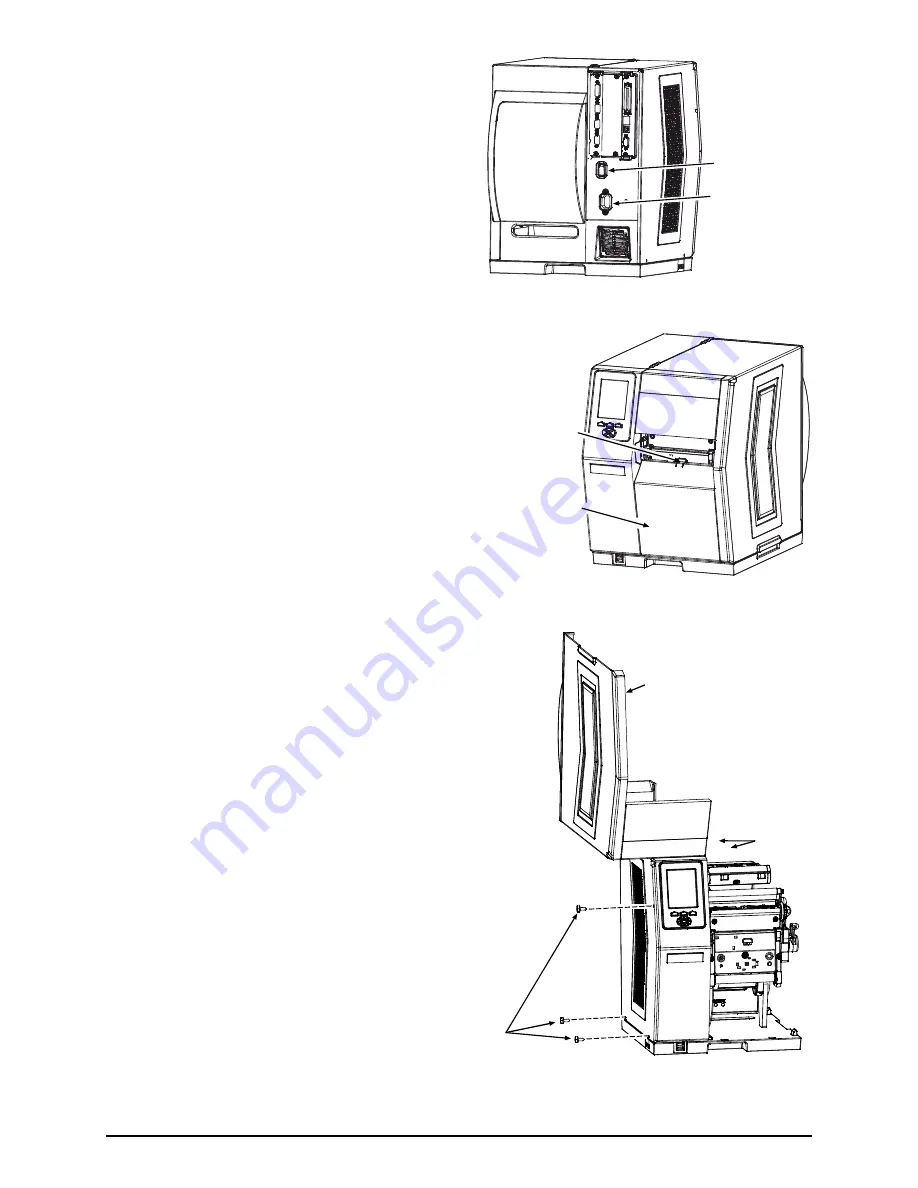
1)   Turn OFF the 

Power Switch

 and unplug the 

power cord from the 

AC Receptacle


AC Receptacle

Power Switch


2)  Press down on the 

Catch

, then pull forward to remove 

the 

Door


Door

Catch


3) Raise 

the 

Cover

. Loosen both 

Hinge 

Screws

. Remove the three 

Cover Screws

and then lift the 

Cover

 off the printer.  

Remove any media and ribbon from the 

printer. 


Cover

Cover

Screws

Hinge

Screws


Содержание H-Class

Страница 1: ...Linear Scanner Option 92 2435 01 Rev C ...

Страница 2: ......

Страница 3: ...installing the kit verify the experience level of the installer the package contents and the tools needed before following the steps below CAUTION Only qualified service personnel should perform this installation For your safety and to avoid printer damage always turn OFF the power switch and unplug the AC power cord before this installation and whenever performing service Contents of the Linear S...

Страница 4: ...ceptacle Power Switch 2 Press down on the Catch then pull forward to remove the Door Door Catch 3 Raise the Cover Loosen both Hinge Screws Remove the three Cover Screws and then lift the Cover off the printer Remove any media and ribbon from the printer Cover Cover Screws Hinge Screws ...

Страница 5: ...nector of the Cable Assembly Item 5 to the Center Plate Aperture using two Screws Item 4 and two Nuts Item 3 Screws Center Plate Aperture Nuts Cable Assembly 6 After routing the Cable Assembly away from movable parts attach its 8 pin connector to J13 of the Backplane CCA Cable Assembly J13 Backplane CCA ...

Страница 6: ...nter Plate using three Screws Item 2 Screws Scanner and Mounting Assembly Center Plate 8 Connect the Scanner Cable to the Center Plate Connector Center Plate Connector Scanner Cable 9 Remove the five Screws that secure the Fascia to the Cover Screws Cover Fascia ...

Страница 7: ...the Fascia to the Cover using the five previously removed Screws Fascia Screws 12 Lower the Cover onto the printer Reinstall and tighten the three Cover Screws Tighten both Hinge Screws Reinstall the Door and lower the Cover Plug the power cord into the AC Receptacle Align the scanner see Alignment section below Door Cover Hinge Screws Cover Screws ...

Страница 8: ... positioning Mounting Bracket Thumbscrew Pivoting Mount Horizontal Mount Scanner Connector Cable LED Goes green to signify a good read Window Portal for image illumination and capture glows red Window LED Scanner CAUTION The Pivot Mount should never be over extended The use of controls adjustments or procedures other than those specified herein may result in hazardous LED light exposure Class 1 LE...

Страница 9: ...For proper recognition the Linear Scanner must be positioned over the bar codes and the codes used and the label layout must meet certain requirements The bar codes must be placed in the picket fence orientation with proper quiet zones and a narrow bar resolution that is no less than the scan resolution position If encoding the same information in multiple up bar codes arranged in ordered columns ...

Страница 10: ...NGS OPTION FEEDBACK Disabled Most settings can be changed via the User Interface as described below Note Before proceeding ensure that the ADVANCED MENU is selected Press MENU then go to SYSTEM SETTINGS MENU MODE ADVANCED MENU and press ENTER WED 09 32A 06NOV2006 OFFLINE PRINTER OPTIONS EXIT ENTER SYSTEM MODULES PRESENT SENSOR CUTTER SCANNER RFID GPIO PORT REWINDER RFID UP DOWN Buttons ENTER Key E...

Страница 11: ... read 0 99 00 The scanner will count the specified number 1 to 99 of bar codes per label if all are not present a fault is declared The default setting 00 enables Auto Mode this mode appropriate for most applications calculates the number of bar codes present and permits a variable number of codes to be read per label See the note below and Label Layout for possible exceptions Note If sent as bitm...

Страница 12: ...ER See table below for listing 3 When finished press EXIT and then YES at the SAVE CHANGES prompt to complete setup Fault Handling Menu Item Description LEVEL Determines the amount of interaction required to proceed after a fault NO REPRINT Printing stops and a fault message is displayed Following correction of the problem FEED must be pressed to clear the fault but the label in process is not rep...

Страница 13: ...e printed if insufficient text space exists or if the fault occurred after the label was printed RETRY COUNT Sets the number of reprint attempts 0 3 If the last label printed in this count has been voided a fault will be declared BACKFEED ON CLEAR Determines the printer s response after a fault is cleared ENABLED After fault clearing backup label positioning will occur DISABLED After fault clearin...

Страница 14: ...avoid printer damage always turn OFF the power switch and unplug the AC power cord before performing service While there is no scheduled maintenance requirement as debris accumulates and performance declines clean the Scanner as follows 1 Turn OFF and unplug the printer 2 Using a Cotton Swab lens tissue or lint free cloth dampened with water carefully wipe the Window clean see illustration Use car...

Страница 15: ...terior of the Linear Scanner Follow the steps below to align the Linear Scanner Note If scanning 5 Mil bar codes change the scanner s position before proceeding see Scan Resolutions 1 Load the printer with four inch 101 mm wide media and ribbon Ensure that the Tear Bar Peel Mechanism or Rewind Plate has been mounted onto the printer If using an external rewinder attach the labels to that device se...

Страница 16: ...roceed accordingly If the green LED is illuminated or if the count increments rapidly press EXIT to end the test see Troubleshooting if problems persist or If the green LED is not illuminated or if the numbers do not increment or increment slowly proceed according the Scan Position 10 Mil Scan Position go to Step 7 or 5 Mil Scan Position go to Step 9 Note When making adjustments avoid contact with...

Страница 17: ...Position Without moving the Pivoting Mount pull the bottom of the Scanner outward and then while observing the LED or the SCAN COUNT slowly pivot the bottom of the Scanner inward until the green LED illuminates continuously or the count increments rapidly Scanner Pivoting Mount 5 Mil Position Without moving the Pivoting Mount push the top of the Scanner inward and then while observing the LED or t...

Страница 18: ...ccording to the Scan Position 10 Mil Position Carefully tighten the Mounting Adjustment Screw Mounting Adjustment Screw 5 Mil Position Carefully tighten the Locking Screw on the right side of the Scanner Locking Screw ...

Страница 19: ...ion 10 Mil Position Carefully raise the Pivoting Mount and then tighten the Locking Screw Carefully lower the Pivoting Mount Locking Screw Pivoting Mount 5 Mil Position Carefully tighten the Mounting Adjustment Screw Mounting Adjustment Screw ...

Страница 20: ...abel and tighten the Thumbscrew Observe the LED or the SCAN COUNT then proceed accordingly If the green LED is illuminated or if the count rapidly increments go to Step 14 If the green LED is not illuminated or if the count does not rapidly increment restart the alignment beginning at Step 6 Note If using the 5 Mil Scan Position loosen the Mounting Adjustment Screw and the Locking Screws before re...

Страница 21: ...e Mounting Bracket 3 Slightly raise the Pivoting Mount Remove the Locking Screws and then lower the Scanner While supporting the Scanner in the Pivoting Mount remove the Mounting Adjustment Screw Scanner Mounting Adjustment Screw Pivoting Mount Locking Screws 4 Align the Scanner to the 5 Mil Position Holes in the Pivoting Mount Install but do not tighten the two Locking Screws Install the Mounting...

Страница 22: ...ed while Enabled Turn OFF the printer Ensure that the Connector Cable is attached look for the red glow on power up otherwise to continue printing without scanning change the MODE setting to Auto or Disabled see Operation Scanner Faults are generated but VOID is not printed on faulted labels Note Normal if the fault occurs after a label printed Ensure the FAULT HANDLING LEVEL is set to VOID AND RE...

Страница 23: ...ected light off the media may be blinding the optics Ensure that the label stock has a matte finish and not a reflective or glossy surface see Operation The label exit angle may have changed Ensure that the Tear Bar Peel Mechanism or Rewind Plate has been mounted to the printer and that the label pathway is unobstructed see the Operator s Manual for details Current scanner settings may be too rest...

Страница 24: ...0 inches 101 mm the10 Mil position and 3 5 inches 89 mm the 5 Mil position Minimum Print Contrast Signal 0 45 min background reflectance of 70 Symbology Orientation Picket fence Electrical Operating Voltage 5 VDC 5 Current Operating 158 mA typical 220 mA maximum Static 150 mA maximum Surge 3 A maximum Environmental Temperature Operating 0 to 40 C 32 to 104 F Storage 10 to 60 C 14 to 140 F Humidity...

Страница 25: ...roduct to the Purchaser at Datamax O Neil s cost With respect to a defect in hardware covered by the warranty the warranty shall continue in effect until the end of the original warranty period or for ninety 90 days after the repair or replacement whichever is later General Warranty Provisions Datamax O Neil makes no warranty as to the design capability capacity or suitability of any of its hardwa...

Страница 26: ......

Отзывы: