VLASE
TM
IR
40
3
3.1.5 CONNECTING THE OPTICAL FIBER ON THE RESONATOR
Follow the steps listed here below to wire the optical fiber to the resonator:
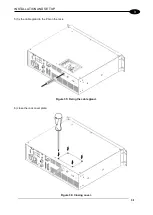
1) unscrew the three screws that secure the metallic cover and cable gland to the resonator.
Figure 37: Disassembling the optical fiber cable gland from the resonator.
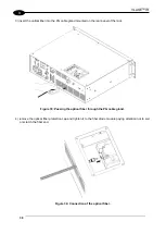
2) insert the optical fiber through the cable gland without removing the
protection cap.
WARNING!
The insertion of the optical fiber is a delicate operation. You must make sure that the optical fiber is
protected by its cap during insertion through the cable gland to avoid damaging or dirtying it.
Figure 38: Passing the optical fiber through the cable gland.
Содержание VLASE IR 1PWX-TLS2
Страница 1: ...USER S MANUAL VLASETM IR ...
Страница 34: ...VLASETM IR 34 2 2 6 CONNECTION EXAMPLES Figure 27 Connection examples ...
Страница 59: ...USE AND OPERATION 59 4 Edit Filling properties such as filling type interline etc using the Properties browser ...
Страница 78: ...VLASETM IR 78 6 6 4 RACK HANDLES Handles for rack fastening are available on request Figure 64 Rack handles ...
Страница 85: ...85 EXTERNAL LABEL PLACING Figure 67 Positioning of external labels rack ...
Страница 86: ...86 Figure 68 Positioning of external labels resonator ...
Страница 90: ...90 BLOCK DIAGRAM VLASETM SAFETY LOGIC DETAILS FOR AUTOMATIC PRODUCTION LINE ...
Страница 108: ...108 APPENDIX G MECHANICAL DRAWINGS ...
Страница 109: ...109 NOTE Please refer to Datalogic website for detailed drawings ...
Страница 112: ......


