INSTALLATION
13
2
PEN Emulation Interface
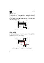
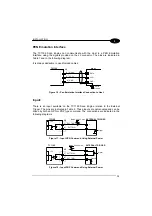
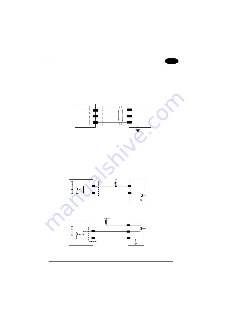
The TC1100 Scan Engine can communicate with the Host in a PEN Emulation
Interface using the signals provided on the J2 connector. The pins are indicated in
Table 1 and in the following diagram:
It is always advisable to use shielded cables.
TC1100
2
5
1
GND
WAND
VCC+
Host
GND
DATA
VCC+
Earth
Ground
J2
Figure 16 – Pen Emulation Interface Connection to Host
Inputs
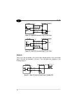
There is an input available on the TC1100 Scan Engine relative to the External
Trigger. The pins are indicated in Table 2. These inputs are optocoupled and can be
driven by both an NPN or PNP type command. The connections are indicated in the
following diagrams:
EXT TRIG+
7
8
+ 5V
TC1100
EXTERNAL TRIGGER
Signal
V
30 Vdc max.
Vext
EXT TRIG-
J2
Figure 17 - Input NPN Command Using External Power
7
8
+ 5V
TC1100
EXTERNAL TRIGGER
30 Vdc max.
Vext
V
Signal
Ground
EXT TRIG+
EXT TRIG-
J2
Figure 18 - Input PNP Command Using External Power
Содержание TC1100
Страница 1: ...TC1100 Installation Manual ...
Страница 2: ...TC1100 Reference Manual ...
Страница 3: ...TC1100 REFERENCE MANUAL ...
Страница 128: ...TC1100 120 A ...


