background image

STEP 5 - INSTALLING DL.CODE CONFIGURATION PROGRAM

PRODUCT REFERENCE GUIDE   

11

Figure 12 - DL.CODE Opening Window

Содержание Matrix 220

Страница 1: ...Matrix 220 PRODUCT REFERENCE GUIDE Image Based Reader...

Страница 2: ...ronic versions of this document may be downloaded from the Datalogic website www datalogic com If you visit our website and would like to make comments or suggestions about this or other Datalogic pub...

Страница 3: ...Step 2 Mount and Position the Reader 3 Step 3 Aim and Autofocus the Reader 5 Step 4 X PRESS Configuration 6 Aim 6 Setup 6 Learn 6 Reset Reader to Factory Default Environment Optional 7 Step 5 Install...

Страница 4: ...echanical Dimensions 55 Mounting And Positioning Matrix 220 60 Mounting Accessory Covers 63 Mounting Flexible Cables 64 Flexible Cables Technical Data 67 ELECTRICAL CONNECTIONS 69 CBX Connection Box P...

Страница 5: ...eader Configuration 121 Auto Calibration 122 Manual Calibration 124 Under exposure 124 Over exposure 125 Moving code out of the Field of View 126 Multi Image Acquisition Settings 127 Automatic Image S...

Страница 6: ...Procedure 175 MAINTENANCE 176 Cleaning 176 TROUBLESHOOTING 177 General Guidelines 177 TECHNICAL FEATURES 180 ALTERNATIVE CONNECTIONS 183 Power Com and I O Connector for Standard Models 183 Com and Tri...

Страница 7: ...when using the reader TECHNICAL SUPPORT Support Through the Website Datalogic provides several services as well as technical support through its website Log on to www datalogic com For quick access fr...

Страница 8: ...pport An excellent source for technical assistance and information is an authorized Datalogic reseller A reseller is acquainted with specific types of businesses application software and computer syst...

Страница 9: ...a flat copper braid shorter than 100 mm connect pin Earth of the CBX connection box to a good Earth Ground for direct connections connect your cable shield to the locking ring nut of the con nector CE...

Страница 10: ...onable protection against harmful interference when the equipment is operated in a commercial environment This equipment generates uses and can radiate radio fre quency energy and if not installed and...

Страница 11: ...to with stand vibration and shock when correctly installed however it is also a precision prod uct and therefore before and during installation it must be handled correctly to avoid damage avoid that...

Страница 12: ...HANDLING xii MATRIX 220 do not weld the reader into position which can cause electrostatic heat or reading window damage do not spray paint near the reader which can cause reading window damage...

Страница 13: ...eral View of DPM Models 1 Reading Window 7 X PRESS Interface 2 Mounting Holes 2 8 Ethernet Connector 3 Power On LED 9 Power COM I O Connector 4 Ethernet Connection LED 10 Power Over Ethernet Connector...

Страница 14: ...of Standard Models 1 Reading Window 7 X PRESS Interface 2 Mounting Holes 2 8 Ethernet Connector 3 Power On LED 9 Power COM I O Connector 4 Ethernet Connection LED 10 Power Over Ethernet Connector 5 90...

Страница 15: ...T REFERENCE GUIDE xv Figure 3 Reading Window Details 1 Lens 5 Non Polarized Illuminator 2 LED Aiming System 6 Polarized Illuminator 3 Red Spot No Read 7 Diffused Illuminators 4 Green Spot Good Read 8...

Страница 16: ...ENERAL VIEW xvi MATRIX 220 Figure 4 Reading Window Details for High Power Illuminator Models 1 Lens 5 Non Polarized Illuminator 2 LED Aiming System 6 Polarized Illuminator 3 Red Spot No Read 7 Standar...

Страница 17: ...PRODUCT REFERENCE GUIDE xvii Figure 5 X PRESS Interface Details 1 Ready Learn 2 Good Setup 3 Trigger Aim 4 COM Test 5 Status 6 Push button NORMAL OPERATION X PRESS CONFIGURATION...

Страница 18: ...GENERAL VIEW xviii MATRIX 220...

Страница 19: ...ansmitted on the RS232 main and or auxiliary interface independently from the Ethernet interface selection When One Shot or Phase Mode Operating mode is used the reader is activated by an External Tri...

Страница 20: ...Outputs O1 Output 1 opto isolated and polarity sensitive O1 Output 1 opto isolated and polarity sensitive O2 Output 2 opto isolated and polarity sensitive O2 Output 2 opto isolated and polarity sensi...

Страница 21: ...position for the reader The most common mounting configuration is shown in the figure below Skew Tilt Figure 7 Positioning with Mounting Bracket 2 When mounting the Matrix 220 take into consideration...

Страница 22: ...3 Refer to the reading diagrams in Chapter 6 Reading Features to determine the dis tance your reader should be positioned at NOTE Rapid Configuration of the Matrix 220 reader can be made either throu...

Страница 23: ...4 Release the button to enter the Aim function The aiming system turns on and the Autofocus procedure begins see Figure 9 The Aim LED will blink until the proce dure is completed Within 3 seconds befo...

Страница 24: ...d The Setup procedure ends when the Image Acquisition parameters are successfully saved in the reader memory the Setup LED will stop blinking and Matrix 220 emits 3 high pitched beeps If the calibrati...

Страница 25: ...emory but the Default configuration is set as the startup configuration NOTE The Grade A Barcode Test Chart cannot be used to set the Code 128 sym bology even though the reader successfully reads the...

Страница 26: ...tract the files maintaining the folder structure and run the start hta file to access the installation pop up Click on the Install DL CODE link to run the installation program and follow the installat...

Страница 27: ...ll also show devices not belonging to the LAN and display them in gray see Figure 10 3 First the device must be added to the LAN by aligning its IP Address to the net work The network administrator sh...

Страница 28: ...device will reappear in the list of Online Devices in color meaning it is now part of the LAN and can be configured The new IP address will also be dis played 7 Double click on or drag the device icon...

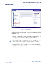
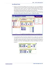
Страница 29: ...STEP 5 INSTALLING DL CODE CONFIGURATION PROGRAM PRODUCT REFERENCE GUIDE 11 Figure 12 DL CODE Opening Window...

Страница 30: ...O PDF417 GS1 DATABAR GS1 DATABAR STACKED GS1 DATABAR LIMITED GS1 DATABAR EXPANDED GS1 DATABAR EXPANDED STACKED UPCEAN FAMILY EAN13 UPCEAN FAMILY EAN8 UPCEAN FAMILY UPCA UPCEAN FAMILY UPCE DATAMATRIX E...

Страница 31: ...ns jobs saved on the device For new devices the only saved job is the Default configuration Click OK The device enters run mode and begins acquir ing images 3 Place the application code in front of th...

Страница 32: ...tic or Dynamic Tuning 1D or 2D code Include Image Filtering to find the best decoding condition For DPM models you can select to use the Polarized or Non Polarized Illuminators 7 Click Start to begin...

Страница 33: ...ng dis tance for your application so that its Field of View covers the application reading area 1 From the Task Area select Open Device Configuration 2 The Open Device Configuration window opens showi...

Страница 34: ...A Barcode Test Chart in the reading area Once positioned stop image acquisition by clicking on the Pause button 5 Click the Image Settings branch and then click the Image Auto Setup button to automati...

Страница 35: ...GUIDE 17 6 Select the Static or Dynamic Self Tuning option Start Autolearn and Apply to the Image Settings After Applying the Image Auto Setup you can see from the Image Settings branch that the Expos...

Страница 36: ...e Reading Distance value is not significant until the Focus Autolearn procedure ends successfully 8 The Calibrate dialog box opens allowing you to start the procedure Click Start For applications havi...

Страница 37: ...At the end of the calibration you can see the new Reading Distance and Image Density PPI values as well as the FOV dimensions Click Apply NOTE To enlarge the visual image of the code view you can cli...

Страница 38: ...ecific code in front of the reader and repeat only the Image Auto Setup to register any changes in lighting or code surface contrast At this point it is probably a good idea to save the configuration...

Страница 39: ...ymbol ogy is not used then delete it from the Code Settings with the Delete icon If you don t know the code type you can use the Code Autolearn feature by click ing on the Code Autolearn icon 1 See th...

Страница 40: ...om the icons over the Configu ration Parameters tree area Continuous One Shot or Phase Mode 2 Configure the relative Operating Mode parameters from the Reading Phase parameters panel Different groups...

Страница 41: ...be selected The following example shows Code Combination By default the Expected Codes when more than one code type is selected are in logical AND which means that all codes are required to be decode...

Страница 42: ...Formatting Message s from the Configu ration Parameters tree area Message 1 Message 2 etc You can add fields to the output message by clicking on the icons above the Message Field area They will be ap...

Страница 43: ...1 Configure your application specific Digital Output s and Green Red Spots if used from the Configuration Parameters tree area Output 1 Output 2 etc NOTE Save the configuration from temporary memory...

Страница 44: ...s on 2 Release the button to enter the Test function Once entered the Bar Graph on the five LEDs is activated and if the reader starts reading codes the Bar Graph shows the Good Read Rate 3 To exit th...

Страница 45: ...DER CONFIGURATION For further details on advanced product configuration refer to the DL CODE User s Guide available in the DL CODE Help menu Host Mode Programming The reader can also be partially conf...

Страница 46: ...e reading flexibility High Power Illuminator models provide double the lighting power and are therefore indicated for high speed applications In addition the Continuous High Power lighting mode can be...

Страница 47: ...ls code reading data formatting serial port and Ethernet interfacing and many other operating and control parameters It is completely user configurable from a Lap top or PC using the dedicated configu...

Страница 48: ...View and to maxi mize the reading performance Windows based DL CODE software to configure the reader parameters via PC Ethernet interface User defined database of Image Acquisition Settings parameter...

Страница 49: ...O IEC 18004 ISO IEC 15416 and AIM DPM standards for code quality trending Match Code option with a user defined match code database Industrial Strength Industrial compact 2D reader Rugged metal constr...

Страница 50: ...low LED indicates active communication on the main serial port Figure 13 4 TRIGGER yellow LED indicates the status of the reading phase Figure 13 5 GOOD green LED confirms successful reading Figure 13...

Страница 51: ...uares Aiming LED Aiming LED Figure 14 Matrix 220 Aiming LEDs LED SPOTS There are two LED spots that can be activated to project light onto the target area to give a visible indication that a particula...

Страница 52: ...peed reader interconnection ID NET is in addition to the Main and Auxiliary serial interfaces The following network configurations are available ID NET Synchronized Single station multiple readers ID...

Страница 53: ...typically located far away from each other and they can have different operating modes from each other At the end of each reading phase each reader transmits its own data message to the host Thanks t...

Страница 54: ...presented by means of the five colored LEDs whereas the single push button gives immediate access to the following relevant functions Test with bar graph visualization to check static reading performa...

Страница 55: ...ivation is as follows Release button to Exit Release button to enter Test Mode Release button to enter Aim Autofocus Mode Release button to enter Setup Mode Release button to enter Learn Mode Release...

Страница 56: ...timeout of about 5 five seconds Matrix 220 will exit without saving the parameters to memory the Setup LED will stop blinking and in this case Matrix 220 emits a long low pitched beep Learn Once enter...

Страница 57: ...s about specific error conditions See the Diagnostic Error Conditions chart in the Diagnostic page of the DL CODE Monitor Ready Blink Good Trigger COM Status Blink MODEL DESCRIPTION Matrix 220 readers...

Страница 58: ...f three different types of Illuminators which can be selected individually depending on the Direct Part Mark application requirements There are Red or Blue light DPM models DPM High Power Illuminator...

Страница 59: ...olarized DPM Blue Diffused Top Bottom Diffused Top Diffused Bottom Non Polarized Polarized Standard High Power White Central Top Bottom Chain Central Chain Top Bottom Chain Standard High Power Red Cen...

Страница 60: ...220 382 040 1 2MP DPM R 7MM POE 937900007 MATRIX 220 385 040 1 2MP DPM R 12MM POE 937900008 MATRIX 220 345 010 1 2MP STD W 12MM HP 937900009 MATRIX 220 305 010 1 2MP DPM R 12MM HP 937900010 MATRIX 22...

Страница 61: ...hernet Cable 3M for linear and torsion moving applications 93A050126 CAB F ETH M05 M12 IP67 GETH X FLEX CAB5M M12 IP67 Flexible Ethernet Cable 5M for linear and torsion moving applications 93A050127 C...

Страница 62: ...ay 93ACC0037 QLM600 Quick Link Metal Master ID NET Profibus Gateway 93ACC0033 QLM700 Quick Link Metal Master ID NET Profinet I O Gateway 93ACC0038 Various M12 Service Cables and Field Mount Connectors...

Страница 63: ...ress Coded in Data Matrix Symbology for Automated Mail Processing Deformed or Overprinted Code Reading Matrix 220 assures the reading of deformed and or overprinted codes even though damaged or printe...

Страница 64: ...ed on Metal Surface by Using Dot Peening Technology Figure 22 Dot Peening Marking on Metal Surface with Multi dot per Code Element Figure 23 Directly Marked Dot Matrix Code Characterized by Outstandin...

Страница 65: ...rinted in different colors Figure 25 Data Matrix Codes Printed in Color or on Colored Backgrounds Laser Marking Etching Technology Figure 26 Data Matrix Code Directly Marked on PCB Surface by Using La...

Страница 66: ...ire product package or printed material This enables easy reliable optical capture without interfer ing with design aesthetics Figure 27 Digimarc Barcode distributed on all sides of the packaging DWCO...

Страница 67: ...marc technology and application examples download our Digimarc Technical Note from Datalogic website For quick access from the home page click on the search icon and type in Digimarc This allows you a...

Страница 68: ...ves particularly useful in the following cases To adjust contrast when the outer area of the image is less exposed than the cen tral area because of a large Skew angle HDR disabled HDR enabled To adju...

Страница 69: ...coded After enabling HDR all four codes are decoded In high speed applications because Exposition Time can be reduced when HDR is enabled The allowed Exposition Time Texp must be less than the code re...

Страница 70: ...al maximum application speed of 3300 mm s For more details on line speed and exposure time calculations refer to Maximum Line Speed and Exposure Time Calculations on page 119 To enable the HDR functio...

Страница 71: ...which mainly emits at the wavelength of 365nm therefore it is recom mended to use an ink sensitive to this wavelength The device also includes a 415nm Long Pass filter placed in front of the receivin...

Страница 72: ...kaging the list of parts includes Matrix 220 reader w connector plug cover Quick Reference Guide Test Chart Mounting Kit Mounting Screws 2 Washers 2 Mounting Bracket Figure 30 Package Contents For Eth...

Страница 73: ...e diagrams below give the overall dimensions of the reader and may be used for its installation Refer to page 60 for various mounting solutions and correct positioning and Chapter 6 Reading Features f...

Страница 74: ...n 2 4 mm x 47 1 85 58 2 30 58 2 26 37 6 1 48 3 0 12 20 5 0 81 38 1 50 mm inch optical axis optical axis INSTALLATION 56 MATRIX 220 Figure 32 Overall Dimensions Standard Models Connector at 90...

Страница 75: ...11 n 2 4 mm 37 6 1 48 20 5 0 81 78 3 07 43 1 68 43 1 68 x 3 0 12 mm inch optical axis optical axis MECHANICAL DIMENSIONS PRODUCT REFERENCE GUIDE 57 Figure 33 Overall Dimensions with Accessory Cover ES...

Страница 76: ...48 37 6 1 48 58 2 26 20 5 0 81 n 2 4 mm 8 0 32 28 1 1 11 43 1 68 x 3 0 12 mm inch optical axis optical axis INSTALLATION 58 MATRIX 220 Figure 34 Overall Dimensions with Accessory Cover ESD or YAG Con...

Страница 77: ...65 2 56 2 5 0 10 3 5 0 1 4 20 13 0 51 2 5 0 10 29 5 1 16 2 0 n 4 9 0 mm inch MECHANICAL DIMENSIONS PRODUCT REFERENCE GUIDE 59 Figure 35 Mounting Bracket Overall Dimensions...

Страница 78: ...ATRIX 220 MOUNTING AND POSITIONING MATRIX 220 Using the Matrix 220 mounting brackets you can obtain rotation on the various axes of the reader as shown in the diagram below Figure 36 Positioning with...

Страница 79: ...fying the Skew angle The Pitch Skew and Tilt angles are represented in Figure 37 Follow the suggestions below for the best orientation Position the reader in order to avoid the direct reflection of th...

Страница 80: ...INSTALLATION 62 MATRIX 220 Figure 38 Tilt Angle Considerations See Chapter 6 Reading Features for FOV vs Reading Distance considerations...

Страница 81: ...ver the Matrix 220 reader and press down on the cover frame edges until the screw holes align To avoid damage do not press on the window 4 Insert one of the screws to avoid damage to the threads turn...

Страница 82: ...elow give the overall dimensions of the cables and may be used for their installation on a Matrix 220 reader with connectors positioned at 0 and 90 NOTE NOTE Figure 40 Flexible power cable connected t...

Страница 83: ...NG FLEXIBLE CABLES PRODUCT REFERENCE GUIDE 65 Figure 41 Flexible power cable connected to Matrix reader with connector at 90 Figure 42 Flexible Ethernet cable connected to Matrix reader with connector...

Страница 84: ...INSTALLATION 66 MATRIX 220 Figure 43 Flexible Ethernet cable connected to Matrix reader with connector at 90 Figure 44 Flexible Power Ethernet cables connected to Matrix reader with connector at 0...

Страница 85: ...d to Matrix reader with connector at 90 Flexible Cables Technical Data Dynamic values for 3D e chain Max Speed 180 s Max Acceleration 60 s2 Min Binding Radius 105 mm Cycles 5 million Dynamic values fo...

Страница 86: ...ty insensitive I1A I1B I2 Polarity insensitive I2A I2B O1 O1 O2 O2 SERIAL MAIN RS232 RX TX IDNET ID ID SHIELD CONNECTOR CASE NOTE INSTALLATION 68 MATRIX 220 For more information on alternative connect...

Страница 87: ...connections through one of the CBX connection boxes since they offer the advantages of easy connection easy device replacement opto iso lated outputs Outputs 1 and 2 and filtered reference signals NO...

Страница 88: ...t 2 A polarity insensitive I2B Input 2 B polarity insensitive V Power Reference Inputs Outputs V Power Source Outputs V Power Reference Outputs O1 Output 1 opto isolated and polarity sensitive O1 Outp...

Страница 89: ...14 16 8 OUT2 11 9 OUT1 8 17 CO TX 2 11 C2 RX 3 12 C1 RTS 4 10 C3 CTS 5 4 TXA 21 14 RXA 20 7 NET 23 15 NET 24 NUT SHIELD 1 12 15 17 22 Not connected To avoid electromagnetic interference when the read...

Страница 90: ...n Figure 46 Power Supply Earth Ground V in VGND Figure 46 Power Supply Connections The power must be between 10 and 30 Vdc only It is recommended to connect the device CHASSIS to earth ground Earth by...

Страница 91: ...ternative A Mid and Endspan or Alternative B MAIN SERIAL INTERFACE The signals relative to the following serial interface types are available on the CBX spring clamp terminal blocks The main serial in...

Страница 92: ...e overall maximum cable length must be less than 15 m 49 2 ft User Interface Reader RX TX SGND TXD RXD SGND Figure 48 RS232 Main Interface Connections RS422 Full Duplex Interface The RS422 full duplex...

Страница 93: ...22 SGND TX TX Figure 50 RS422 Full Duplex Connections Using Only TX Signals to Host ID NET INTERFACE CBX100 500 Description Shield Network Cable Shield ID ID NET Network Data ID ID NET Network Data RE...

Страница 94: ...th depends on the baudrate used see the Baudrate Table below For Common Power Connections use only 2 wires ID and ID DC Voltage Power cable Vdc GND should be handled as a signal cable i e do not put i...

Страница 95: ...figure shows the response time of the ID NET network This time is defined as the period between the Trigger activation and the beginning of data trans mission to the Host Figure 51 ID NET Response Ti...

Страница 96: ...The network must be properly terminated in the first and last reader of the network This is done by setting the ID NET Termination Resistance Switch in the CBX100 500 to ON ID NET Connection Diagrams...

Страница 97: ...ID NET INTERFACE PRODUCT REFERENCE GUIDE 79 Figure 53 ID NET Network Connections with Common Power Branch Network...

Страница 98: ...ELECTRICAL CONNECTIONS 80 MATRIX 220 Figure 54 ID NET Network Connections with Common Power Star Network...

Страница 99: ...DL CODE The 9 pin female Auxiliary Interface connector inside the CBX is the preferred connector for temporary communication monitoring 1 5 6 9 Figure 55 9 pin female connector If permanent system wir...

Страница 100: ...te of these inputs are selected in software An anti disturbance filter by default is implemented in software on both inputs The value can be changed through the software parameter Debounce Filter See...

Страница 101: ...er Figure 56 PNP External Trigger Using Matrix 220 Power CAUTION Power from the Vdc GND spring clamps is available directly to the Input Device on the V V spring clamps and does not pass through the P...

Страница 102: ...ELECTRICAL CONNECTIONS 84 MATRIX 220 Figure 57 NPN External Trigger Using Matrix 220 Power...

Страница 103: ...evice Reference Figure 58 PNP External Trigger Using External Power NPN Photocell Input Signal Pulled up to External Input Device Power Figure 59 NPN External Trigger Using External Power CBX100 500 D...

Страница 104: ...Using Matrix 220 Power Input Device Power to Input Device Input Device Reference Input Signal Figure 61 NPN Input 2 Using Matrix 220 Power CAUTION Power from the Vdc GND spring clamps is available di...

Страница 105: ...Input Device Input Signal Figure 62 PNP Input 2 Using External Power Input Device Input Signal Pulled up to External Input Device Power Figure 63 NPN Input 2 Using External Power Input 3 Connections C...

Страница 106: ...0 mA max 30 Vdc VCE saturation 1 Vdc max 10 mA VOUT ILOAD 100 mA max 3 Vdc PD 90 mW Max 50 C ambient temp ILOAD max 100 mA By default Output 1 is associated with the No Read event which activates whe...

Страница 107: ...to Out put Device Output Device Reference Output Signal Figure 66 NPN Open Collector Output Using Matrix 220 Power Output 1 and 2 Connections Using External Power Output 2 Device Output Signal Output...

Страница 108: ...NNECTIONS 90 MATRIX 220 Figure 68 NPN Open Collector Output Using External Power Output 3 is not opto isolated but can be assigned to the same events By default it is not assigned to any event The CBX...

Страница 109: ...ice Output Device Reference Output Signal Output 3 Device Figure 69 Output 3 Using Matrix 220 Power Output 3 Connections Using External Power CBX500 Only Output Device Reference Output Signal Output 3...

Страница 110: ...be used to connect to a LAN On the Matrix 220 on board Ethernet interface the following communication channels are available TCP Client TCP Server UDP Channel FTP Client The following Fieldbus protoc...

Страница 111: ...ERIAL HOST The following table contains the pinout for standard RS232 PC Host interface For other user interface types please refer to their own manual RS232 PC side Connections 9 pin male connector 2...

Страница 112: ...w information models for specific industries can be created The specifications of these models are called Companion Specifications A number of Com panion Specifications have already been created Datal...

Страница 113: ...s Settings OPC UA Settings Figure 72 Enabling OPC UA Server on DL CODE The user can also set a username and a password to access the OPC UA device To enable protection go to Device Settings Security S...

Страница 114: ...hrough DL CODE which connects to the reader through the on board Ethernet interface DL CODE now supports several different multi device configuration types using the PASS THROUGH configuration In part...

Страница 115: ...a CAB ETH X M0x cable There is no need to use a crossover adapter since Matrix 220 incorporates an autocross function PG6000 Host CAB DSxx S Matrix 220 CAB ETH X M0x CBX Ethernet Interface Auxiliary...

Страница 116: ...AB ETH X M0x cables Host CAB DSxx S Matrix 220 CAB ETH X M0x Ethernet Interface Auxiliary Serial Interface RS232 Data Monitor External Trigger for One Shot or Phase Mode Alone Alone Alone CBX CBX Swit...

Страница 117: ...n interface selection to monitor data When One Shot or Phase Mode operating mode is used the reader can be activated by an External Trigger for example a pulse from a photoelectric sensor when the obj...

Страница 118: ...ransmitted on the RS232 auxiliary interface independently from the Field bus interface selection to monitor data When One Shot or Phase Mode operating mode is used the reader can be activated by an Ex...

Страница 119: ...l Interface RS232 or RS422 Full Duplex Auxiliary Serial Interface RS232 Pass through Input Channel Output Channel Alone Alone Alone CBX Switch Power Mode Continuous Mode External Trigger Figure 79 Pas...

Страница 120: ...terface RS232 or RS422 Full Duplex Auxiliary Serial Interface RS232 Pass through Input Channel Output Channel Alone Alone Alone CBX Switch Power Mode Continuous Mode External Trigger ID NET Master ID...

Страница 121: ...the following examples the RS232 RS422 main serial interface is used For a Master Slave Synchronized layout the External Trigger signal is unique to the sys tem there is a single reading phase and a s...

Страница 122: ...Ext Power BA500 Trigger BA300 Service Figure 82 ID NET Synchronized Layout Matrix 220 Master with CBX500 Matrix 220 Slaves with QL100 If the Backup and Restore function is not required then a QL300 c...

Страница 123: ...Layout with Master on board TCP IP Ethernet Interface to Host Alternatively the Master reader can communicate to the Host as a Slave node on a Fieldbus network This requires using an accessory Fieldb...

Страница 124: ...gle Diagonal MinReading Distance mm 7 mm F 4 11 mm 38 29 48 40 mm 12 mm F 5 4 mm 24 18 30 40 mm The viewing angle has a tolerance of 1 depending on the reading distance FOVx 2 d d0 tan ax 2 where FOVx...

Страница 125: ...nding on the code resolution symbology and number of characters in the code the Reading Area can be different from the FOV See the Reading Diagrams starting on page 112 for specific reading area examp...

Страница 126: ...READING FEATURES 108 MATRIX 220 7 mm Models 38 Horizontal View Angle 1D Horizontal FoV Reading Distance mm Code 128 Figure 87 7 mm Global FOV Diagram...

Страница 127: ...DIAGRAMS PRODUCT REFERENCE GUIDE 109 2D Data Matrix Horizontal FoV Reading Distance mm ECC 200 Figure 88 7 mm Global FOV Diagram Digimarc Barcode Reading Distance Horizontal FoV Figure 89 7 mm Global...

Страница 128: ...ATRIX 220 12 mm Models 24 Horizontal View Angle Horizontal FoV Reading Distance mm 1D Code 128 Figure 90 12 mm Global FOV Diagram Horizontal FoV Reading Distance mm 2D Data Matrix ECC 200 Figure 91 12...

Страница 129: ...GLOBAL FOV DIAGRAMS PRODUCT REFERENCE GUIDE 111 Digimarc Barcode Reading Distance Horizontal FoV Figure 92 12 mm Global FOV Diagram...

Страница 130: ...Common software parameter settings other than default settings are For reading 1D code symbologies Narrow Quiet Zone Enabled For reading 2D code symbologies Code Contrast Standard Decoding Complex it...

Страница 131: ...1 2 3 4 5 5 4 3 2 1 8 9 10 11 12 14 13 0 inch mm Conditions Hardware Settings Code Symbology Code 128 Code Resolution 8 mils Tilt Angle 0 Skew Angle 15 Focusing Distance 300 mm Software Parameters Re...

Страница 132: ...Distance Horizontal FoV 6 2 4 8 8 6 4 2 8 20 10 18 12 14 16 0 inch mm Conditions Hardware Settings Code Symbology Code 128 Code Resolution 12 mils Tilt Angle 0 Skew Angle 15 Focusing Distance 400 mm...

Страница 133: ...0 0 5 2 0 2 5 3 0 3 5 4 0 0 inch mm 4 5 Conditions Hardware Settings Code Symbology Data Matrix ECC 200 Code Resolution 5 mils Tilt Angle 0 Skew Angle 15 Focusing Distance 95 mm Software Parameters R...

Страница 134: ...1 2 3 3 2 1 8 9 10 11 12 13 0 inch mm Conditions Hardware Settings Code Symbology Code 128 Code Resolution 6 mils Tilt Angle 0 Skew Angle 15 Focusing Distance 300 mm Software Parameters Reader Model...

Страница 135: ...2 3 4 5 5 4 3 2 1 16 17 18 19 20 22 21 0 inch mm 23 24 25 6 6 Conditions Hardware Settings Code Symbology Code 128 Code Resolution 10 mils Tilt Angle 0 Skew Angle 15 Focusing Distance 560 mm Software...

Страница 136: ...5 0 inch mm 3 25 Conditions Hardware Settings Code Symbol ogy Data Matrix ECC 200 Code Resolu tion 3 mils Tilt Angle 0 Skew Angle 15 Focusing Dis tance 102 mm Software Parameters Reader Model STD 355...

Страница 137: ...or the specific application It can be evaluated in static reading conditions and depends on the Matrix reader model selected for the application internal lighting system optical lens reading distance...

Страница 138: ...de resolution i e 2X There is a decrement of overlapping effects between two adjacent ele ments Tilt Angle maximum speed decreases when increasing Tilt angle from 0 to 45 degrees The Internal Lighting...

Страница 139: ...top or PC that meets or exceeds the following 2 00 GHz or faster microprocessor Windows 7 8 1 or 10 1 GB RAM 2 GB hard disk for 64 bit machines 1 GB hard disk for 32 bit machines 100 Base T Ethernet O...

Страница 140: ...aximize the reading performance by tuning the acquisition parameters photometry automatically By selecting the Image Auto Setup tool from the Image Settings branch in the Advanced Setup step the follo...

Страница 141: ...Dynamic Self Tuning option Start Image Auto Setup and Apply to the Image Settings The Advanced Setup window works interactively so that you can see the results of the parameter setting changes as wel...

Страница 142: ...eters in their order of appearance 1 increase the Exposure Time 2 increase the Gain NOTE Figure 94 Example Under Exposure Too Dark In general a longer exposure time corresponds to a lighter image but...

Страница 143: ...REFERENCE GUIDE 125 Over exposure To correct this result it is recommended to change the following parameters in their order of appearance 1 decrease the Gain 2 decrease the Exposure Time Figure 95 Ex...

Страница 144: ...t this result and have the code completely visible in FOV it is possible to follow one or both the procedures listed below reposition the reader use the Delay on Trigger and set the Time or Space valu...

Страница 145: ...r selectively by an activa tion event For example an application may have several stable but different lighting conditions which require different lighting options One Image Acquisition Setting could...

Страница 146: ...read rate through the Start Acquisition From parameter By choosing the Last Successful value we will start with the Image Setting that last produced a Good Read For this group of items the last Image...

Страница 147: ...and therefore we can pre select the correct Image Setting from an external source When the Image Settings Selection is External Acquisition Sequences are created and by default each Image Setting has...

Страница 148: ...Sequence box Select the empty Sequence box and delete it with the delete key Each Acquisition Sequence can be activated exclusively by a single event either through a string from an available communic...

Страница 149: ...icking on the Add Cropping Region icon as shown below In Matrix 220 the frame rate is dependent on the number of rows and columns in the defined window Image cropping allows reducing the Image process...

Страница 150: ...X 220 By dragging the edges with the mouse resizing you can crop the image to a specific location where codes are present The numbers in the blue boxes refer to pixel refer ences The cropped area can...

Страница 151: ...AGE CROPPING PRODUCT REFERENCE GUIDE 133 You can also set the cropped image size and position through the Cropping Region Area group of parameters size Width and Height position Left Top x y coordinat...

Страница 152: ...nt mark quality and or relatively normal size codes This is the default setting Very High can improve the decode rate for low print mark quality and or small size codes This algorithm is much more agg...

Страница 153: ...hite Non Polarized Polarized Diffused External LT 510 Printed codes on opaque paper or labels having a flat surface Laser Etching or Ink Jet code marking on an opaque flat sur face having no evident m...

Страница 154: ...olor becomes brighter on the other hand when illumi nated with an opposite color it appears darker see the Chromatic Circle Chart Consequently during the reading phase the lighting system changes the...

Страница 155: ...d code on dark background Black printed code on red background Blue printed code on light background White printed code on blue background Blue printed code on dark background Black printed code on bl...

Страница 156: ...mage If this glare covers the code the reader will not be able to see it and therefore cannot decode it see the first image in the table below Application Characteristics Non Polarized Polarized Diffu...

Страница 157: ...ver for the Polarized illuminator the contrast is not sufficient no matter what the position in the FoV Application Characteristics Non Polarized Illuminator Reading a Data Matrix code etched on a met...

Страница 158: ...ode or group of codes in one or more Image Settings See the DL CODE User s Manual for examples of Image Filter application The Erode Filter enlarges the image dark zones to increase readability Before...

Страница 159: ...e image Before No Read After Readable The Contrast Stretching filter maximizes image contrast Before No Read After Readable The Contrast Stretching filter maximizes image contrast Before No Read After...

Страница 160: ...niform Before No Read After Readable The Smoothing filter deletes small insignificant details in the center of the image Before No Read After Readable The Sharpening filter improves out of focus image...

Страница 161: ...adable The Deblurring filter improves blurred images Before No Read After Readable The Black Enhancement filter produces a nonlinear increase in the black level for light images Before No Read After R...

Страница 162: ...ix 220 readers support pass through multi device configurations The pass through configuration allows individually working devices Alone to collect data from other devices also working Alone and pass...

Страница 163: ...PASS THROUGH CONFIGURATIONS PRODUCT REFERENCE GUIDE 145...

Страница 164: ...h factory default settings Layout Type Alone Inter nal Network Role Slave 2 Run DL CODE and verify that all the devices are discovered and shown in the device list area 3 Connect to the designated Mas...

Страница 165: ...e to assign as ID NET Master current default setting is Slave Click on Setup Internal Network Configuration from the Task area You will be advised that the device role will be changed to Master Click...

Страница 166: ...operation by clicking on the Start Net Autoset button Depending on the application select one of the Default Internal Network Configura tions Multidata Synchronized Phase Mode or Synchronized PackTra...

Страница 167: ...ked Slave configurations will remain as Temp configurations and you will be warned that changes to the Master have not been saved to the Cluster For Multidata configurations the option to Clone Master...

Страница 168: ...SOFTWARE CONFIGURATION 150 MATRIX 220 Open the Slave specific application job it will either have the new name saved from the Master or Temp depending on the Save on Slave Device selection...

Страница 169: ...TIONS PRODUCT REFERENCE GUIDE 151 When the configuration opens pause run mode and set all the application specific con figuration parameters including Image Settings Verify the focus and decoding with...

Страница 170: ...rk is configured The following screenshots show the pass through configuration settings 1 If Save on Slave Device was selected when saving the Master configuration an application job with the same nam...

Страница 171: ...INTERNAL NETWORK CONFIGURATIONS PRODUCT REFERENCE GUIDE 153...

Страница 172: ...ation of all the application parameters including Image Set tings and save them to the Master with an application relative name and with the option to Clone Master configuration on Slaves Figure 100 S...

Страница 173: ...INTERNAL NETWORK CONFIGURATIONS PRODUCT REFERENCE GUIDE 155 Open the cloned application job...

Страница 174: ...ters Image Auto Setup feature in the Advanced Setup Image Settings step Acquisition Trigger Delays necessary to avoid lighting interference between adja cent or oppositely positioned readers Reading P...

Страница 175: ...device until the entire network is configured See ID NET Synchronized Network on page 103 for an example 1 An application job with the same name as the Master s has been cloned to the Slaves Each Sla...

Страница 176: ...necessary as a troubleshooting tip you can temporarily apply the Reading Mask field in place of each Code Content field to verify if all devices are reading To do this 1 Connect to the Master device v...

Страница 177: ...1 to 31 by default from right to left Example Master Slave 1 00000000000000000000000000000011 The figure above shows that both the Master and Slave 1 are reading Code 128 while only the Master is read...

Страница 178: ...the bottom of the screen By selecting the various configuration steps above you can visualize the slave configura tion NOTE You can modify some Slave Synchronized parameters from this view but you can...

Страница 179: ...rforming Complete Configuration and Environ ment parameter storage for Single Reader and ID NET Master Slave network devices as well as device firmware Backup and Restore can be applied to any reader...

Страница 180: ...that configuration in temporary memory will not be saved so you should save the configuration to the reader before performing Backup If you are performing a backup to a file you will be asked whether...

Страница 181: ...provides easy and secure Single Device Replacement 1 Remove the device to be replaced 2 Connect the new device make sure the new device has been previously set to fac tory default 3 Run the Restore p...

Страница 182: ...and Position in a Network Ethernet ID NET etc and are not influenced by the Default or any other Con figuration present in memory Restore Default Startup Configuration The Default configuration is alw...

Страница 183: ...Any previously saved configurations on the device will remain in memory but the Default configuration is set as the startup configuration Restore Factory Defaults In order to return a device to its a...

Страница 184: ...220 DIAGNOSTIC ALARMS By using the DL CODE Monitor functions from the File menu or Monitor icon you can get information about diagnostic alarms Any alarms will show up as warning lights on the alarm p...

Страница 185: ...ding performance can be viewed by enabling the Statistics panel from the DL CODE Monitor item selected from the File menu or Monitor icon Figure 103 Reading Statistics The enabled Statistical Counters...

Страница 186: ...DL CODE BM150 must be detected through the BM100 backup memory module at power up reset and this is done through a command setting in DL CODE By connecting the reader to DL CODE the following paramete...

Страница 187: ...ead a code and store it as the Match code View Menu Master Only Exit returns to Main menu Standard displays the Standard Reading Results screen during run mode Reading Mask displays the Reading Mask o...

Страница 188: ...NOTE NOTE NOTE When the HMI Interface is entered from either the Local Device reader or Remote Device BM150 the key s on the other device are disabled When the reader is connected to DL CODE access to...

Страница 189: ...scanner model K software STD Standard SS Special V software version R Device Network Type MUL Multidata SYN Synchronized ALN Alone N Device Network Setting M00 ID NET Network Master Sxx ID NET Networ...

Страница 190: ...d ALN Alone N Device Network Setting M00 ID NET Network Master Sxx ID NET Network Slave address Null string Alone no network Alarm Code Description 1 Slave No Reply 64 Slave Address Duplication 171 Pr...

Страница 191: ...ultiple Read X code content Y number of codes read Reading Mask Only Master Only X code content or No Read or Multiple Read Y Good Read No Read Multiple Read and Partial Read counters on the last 100...

Страница 192: ...aster plus Slave readers 1 15 0 No Read 1 Good Read M Multiple Read U Diagnostic condition for Stand Alone or Master plus Slave readers 1 15 reader OK reader not detected at startup reader detected at...

Страница 193: ...meter storage of only the Startup Con figuration for the Master and all Slaves present in the network The Slaves must always be configured with the same network baudrate as the Master for correct func...

Страница 194: ...inued correct operation of the reader See General View on page xiii Dust dirt etc on the lens cover may alter the reading performance Repeat the operation frequently in particularly dirty environments...

Страница 195: ...suggest providing if possible Application Program version Parameter Configuration file Serial Number and Order Number of your reader You can get most of this information while DL CODE is connected to...

Страница 196: ...blinking On the Reading Phase step check the settings for Acquisition Trigger Reading Phase ON and Reading Phase OFF parame ters Are the COM port parameters Baud Rate Parity Data Bits Stop Bits correc...

Страница 197: ...in Serial Port TX or Main Serial Port RX Communication data transferred to the host are incorrect corrupted or incom plete Are the host serial port settings the same as the reader serial port settings...

Страница 198: ...UA Inputs Input 1 External Trigger and Input 2 Opto coupled and polarity insensitive Max Voltage 30 Vdc Max Input Current 10 mA Outputs a a when connected to the CBX connection boxes the electrical f...

Страница 199: ...each axis Shock Resistance EN 60068 2 27 30g 11 ms 3 shocks on each axis Protection Class b b when correctly connected to IP67 cables with seals Cables must be completely tightened to assure sealing...

Страница 200: ...GS1 and Direct Marking QR Code Standard and Direct Marking Micro QR Code MAXICODE Aztec Code Digimarc Barcode Australia Post Royal Mail 4 State Customer Kix Code Japan Post PLANET POSTNET POSTNET BB...

Страница 201: ...Power supply input voltage 2 GND Power supply input voltage Connector case CHASSIS Connector case provides electrical connection to the chassis 6 I1A External Trigger A polarity insensitive 5 I1B Ext...

Страница 202: ...ector 1 I1A External Trigger A polarity insensitive 2 RX RS232 Main Serial Receive data signal 3 TX RS232 Main Serial Transmit data signal 4 I1B External Trigger B polarity insensitive 5 GND RS232 Mai...

Страница 203: ...board Ethernet connection This interface is IEEE 802 3 10 BaseT and IEEE 802 3u 100 BaseTx compliant Figure 3 M12 X Coded Female Ethernet Network Connector 1 TX Transmit data 2 TX Transmit data 3 RX R...

Страница 204: ...t Network Connector 1 TX Transmit data 2 TX Transmit data 3 RX Receive data 4 RX Receive data 5 DC1 DC power 6 DC2 DC power 7 DC1 DC power 8 DC2 DC power Power can be applied to any of the data pairs...

Страница 205: ...TS Three general purpose non opto isolated but short circuit protected outputs are avail able on the M12 17 pin connector The pinout is the following 9 O1 Configurable digital output 1 8 O2 Configurab...

Страница 206: ...oltage Vdc otherwise correct output functioning cannot be guaranteed CAUTION For Matrix 220 PoE models the internal Digital Output circuitry is not powered and supply power is not available to any Inp...

Страница 207: ...tor 25 pin male connector Pin Name Pin Name 2 RX 3 RX 3 TX 2 TX 5 GND 7 GND How To Build A Simple Interface Test Cable The following wiring diagram shows a simple test cable including power external p...

Страница 208: ...stem A collection of ROM based code with a standard API used to interface with standard PC hardware Bit Binary digit One bit is the basic unit of binary information Generally eight consecutive bits co...

Страница 209: ...emical etching etc EEPROM Electrically Erasable Programmable Read Only Memory An on board non volatile mem ory chip Element The basic unit of data encoding in a 1D or 2D symbol A single bar space cell...

Страница 210: ...LED technology used as an extended lighting source in which extra optics added to the chip allow it to emit a complex radiated light pattern Matrix Symbologies 2D Codes An arrangement of regular poly...

Страница 211: ......

Страница 212: ...ight no part of this documentation may be repro duced stored in or introduced into a retrieval system or transmitted in any form or by any means or for any purpose without the express written permissi...

Отзывы: