Datalogic Matrix 210 Скачать руководство пользователя страница 29

MATRIX 210™ QUICK GUIDE 


29


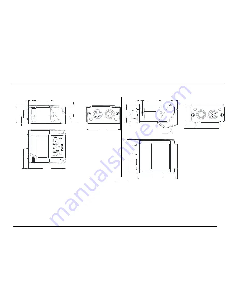
MECHANICAL DIMENSIONS 


45

[1.76]

10.

0

[0

.3

9]

25.0

 [0.98]

11.

0

 [0.

43]

25

 [0

.9

8]

50

[1.97]

7

[0.29]

6

[0.25]

32

[1.25

]

9.0

 [0.36]

25.0

 [0.98]

7

 [0.29]

M3X4

n°4

25

 [0.

9

8]

45

 [1.76]

54

 [2.13]

14

 [0.

5

5]


Figure 17 – Matrix 210™ Overall Dimensions - Straight and 90° Reading Window Models 

mm 

[in] 

OPTICAL 
AXIS 

OPTICAL AXIS

Содержание Matrix 210

Страница 1: ...Labels 6 NOTE This manual illustrates a Stand Alone application For other types of installations such as ID NET Fieldbus Pass Through Multiplexer Layout etc and for a complete reader configuration us...

Страница 2: ...to Collegarsi a www automation datalogic com F Les versions mises jour de drivers et documentation de ce produit sont disponibles sur Internet Cliquez sur www automation datalogic com D Im Internet fi...

Страница 3: ...ners Helpdesk Material Return Authorization LEGAL NOTICES 2011 Datalogic Automation S r l ALL RIGHTS RESERVED Protected to the fullest extent under U S and international laws Copying or altering of th...

Страница 4: ...When One Shot or Phase Mode Operating mode is used the reader is activated by an External Trigger photoelectric sensor when the object enters its reading zone Figure 1 Matrix 210 25 Pin Model in a St...

Страница 5: ...X Auxiliary Interface RX V Power Source Inputs SGND Auxiliary Interface Reference I2A Input 2 A polarity insensitive ID NET I2B Input 2 B polarity insensitive REF Network Reference V Power Reference I...

Страница 6: ...ASSIS Cable shield connected to chassis 18 I1A External Trigger A polarity insensitive 19 I1B External Trigger B polarity insensitive 6 I2A Input 2 A polarity insensitive 10 I2B Input 2 B polarity ins...

Страница 7: ...x64 DPInst64 exe For other operating systems see the readme txt in the Support Files USB Virtual COM Port Drivers directory For updated drivers or more details go to ftdichip com Drivers VCP htm Confi...

Страница 8: ...6 From the Advanced Settings for COMx dialog Expand the COM Port Number menu and select a new COM Port number if desired optional Set the BM Options Latency Timer msec parameter to 1 You are now ready...

Страница 9: ...nal power supply is necessary The default baud rate is 115200 To maximize data transfer you can set it up to 921600 by configuring the reader though the Communication parameters via VisiSet For furthe...

Страница 10: ...the most suitable position for the reader Two of the most common mounting configurations are shown in the figures below Other mounting solutions are provided in the Matrix 210 Reference Manual Figure...

Страница 11: ...inimize Minimize Figure 6 Pitch Skew and Tilt Angles 3 Refer to the Reading Features table in the Appendix of this Quick Reference Guide to determine the distance your reader should be positioned at N...

Страница 12: ...the Aim LED is on 3 Release the button to enter the Aim function The aiming system turns on see Figure 7 4 Place the application specific code in front of the reader at the reading distance indicated...

Страница 13: ...The Setup LED will blink until the procedure is completed The Setup procedure ends when the Image Acquisition parameters are successfully saved in the reader memory the Setup LED will remain on conti...

Страница 14: ...its a long low pitched beep 6 Exit the Setup function by pressing the X PRESS push button once green green yellow yellow red Figure 10 X PRESS Interface Learn Function If you have used this procedure...

Страница 15: ...ored To install VisiSet turn on the PC that will be used for the configuration running Windows 98 2000 NT XP Vista or 7 then insert the VisiSet Mini DVD wait for the DVD to autorun and follow the inst...

Страница 16: ...16 STEP 6 CONFIGURATION USING SETUP WIZARD The Setup Wizard option is advised for rapid configuration or for new users It allows reader configuration in a few easy steps 1 Select the Setup Wizard but...

Страница 17: ...stance see step 2 and the Reading Features table in the Appendix of this Quick Reference Guide 2 Press the Positioning button The reader continuously acquires images and gives visual feedback in the v...

Страница 18: ...a Calibration Mode choice and press the Calibrate button The reader flashes once acquiring the image and auto determines the best exposure and gain settings If the code symbology is enabled by defaul...

Страница 19: ...210 QUICK GUIDE 19 4 Select a Code Setting Mode choice and press the Code Setting button The Setup Result section of the Setup Wizard window shows the code type results and parameter settings Setup Re...

Страница 20: ...Saving Options choice and press the Save button 6 Close the Setup Wizard NOTE If your application has been configured using the VisiSet Setup Wizard your reader is ready If necessary you can use VisiS...

Страница 21: ...elease the button to enter the Test function Once entered the Bar Graph on the five LEDs is activated and if the reader starts reading codes the Bar Graph shows the Good Read Rate In case of no read c...

Страница 22: ...hods ADVANCED CONFIGURATION USING VISISET Advanced configuration can be performed through the VisiSet program by selecting Device Get Configuration From Temporary Memory to open the Parameter Setup wi...

Страница 23: ...to install an Ethernet network ID NET network Fieldbus network Pass Through network Multiplexer network or an RS232 Master Slave refer to the Matrix 210 Reference Manual The reader can also be setup f...

Страница 24: ...f the five LEDs are illustrated in the following table READY green This LED indicates the device is ready to operate GOOD green This LED confirms successful reading TRIGGER yellow This LED indicates t...

Страница 25: ...15 1 97 238 0 20 8 Typ 0 38 15 70 2 76 192 7 55 1 Focus Distance 2 Pixels per inch Focus Distance 3 Measurement Conditions Test Chart provided with the reader Still code at the center of the FOV Code...

Страница 26: ...00 bit s 2400 to 115200 bit s ID NET Up to 1MBaud Up to 1MBaud Ethernet 10 100 Mbit s Inputs Input 1 External Trigger and Input 2 Opto coupled and polarity insensitive Opto coupled and polarity insens...

Страница 27: ...Interleaved 2 of 5 Codabar Code 93 Pharmacode EAN 8 13 UPC A E including Addon 2 and Addon 5 GS1 DataBar Family Composite Symbologies Data Matrix ECC 200 Standard GS1 and Direct Marking QR Code Standa...

Страница 28: ...e ISO IEC 15415 Data Matrix ECC 200 QR Code ISO IEC 15416 Code 128 Code 39 Interleaved 2 of 5 Codabar Code 93 EAN 8 13 UPC A E AS9132A Data Matrix ECC 200 AIM DPM Data Matrix ECC 200 QR Code USER INTE...

Страница 29: ...1 76 10 0 0 39 25 0 0 98 11 0 0 43 25 0 98 50 1 97 7 0 29 6 0 25 32 1 25 9 0 0 36 25 0 0 98 7 0 29 M3X4 n 4 25 0 98 45 1 76 54 2 13 14 0 55 Figure 17 Matrix 210 Overall Dimensions Straight and 90 Rea...

Страница 30: ...0 08 90 19 0 75 12 5 0 49 25 0 98 19 0 75 60 30 12 5 0 49 25 0 98 60 30 6 2 n 3 n 4 S L O T 3 1 ST 337 bracket for 90 Reading Window Model 38 22 0 87 1 50 2 0 08 10 0 39 30 60 60 30 n 4 SLOT 3 1 6 2...

Страница 31: ...ual for the Declaration of Conformity Only connect Ethernet and dataport connections to a network which has routing only within the plant or building and no routing outside the plant or building EMC C...

Страница 32: ...FCC Rules Operation is subject to the following two conditions 1 This device may not cause harmful interference and 2 this device must accept any interference received including interference which may...

Отзывы: