


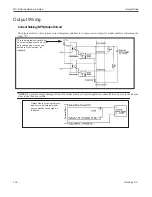


Output Wiring
MX-E Series Hardware Guide
Datalogic S.r.l.
106
Current Sourcing (PNP) Output Circuit
The diagrams below show internal circuit diagrams and how to wire processor outputs for model numbers containing the
letter “P.”
NOTES
: To prevent output damage, all inductive loads must have noise suppressors connected directly across the load, as
close to the load as possible.
This is an internal connection, not
an output voltage source. An exter-
nal power source must be con-
nected to the Load, as indicated.
Output Plus is not an output volt-
age source. An external power
source must be connected, as
indicated.
Содержание E1 Series
Страница 1: ...MX E Series Hardware Guide for Processor and Cameras Revision Date July 19 2018 ...
Страница 4: ......
Страница 18: ...Before You Call MX E Series Hardware Guide Datalogic S r l 12 ...
Страница 28: ...Battery MX E Series Hardware Guide Datalogic S r l 22 ...
Страница 44: ...M2xx and M3xx Camera Connection MX E Series Hardware Guide Datalogic S r l 38 M2xxandM3xxTerminalConnections ...
Страница 56: ...JAI Cameras MX E Series Hardware Guide Datalogic S r l 50 661 0402TerminalBlockDimensions ...
Страница 58: ...JAI Cameras MX E Series Hardware Guide Datalogic S r l 52 JAITerminalConnections sinking ...
Страница 64: ...Basler Cameras MX E Series Hardware Guide Datalogic S r l 58 TerminalConnections ...
Страница 116: ...M1xx and E1xx MX E Series Hardware Guide Datalogic S r l 110 ...
Страница 120: ...Index MX E Series Hardware Guide Datalogic S r l iv ...


