background image


 DataVS1 

Series 


Instruction 

Manual  


18 


achieved the desired position, press the 

TEACH

 button to save the settings and return to the Setup 

menu.  Press the 

ESC

 button to return to the Setup menu without saving the modifications (the system 

will request confirmation on the saving option). 


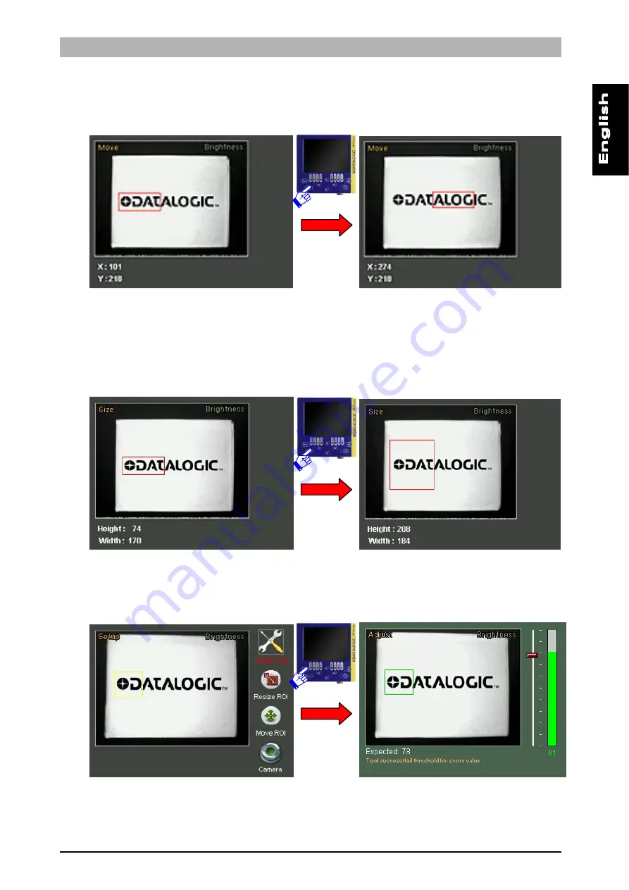
If you wish to modify the ROI size, select the 

Resize ROI 

 from the Setup menu (using the 

SET

 button 

again). It is now possible to increase or decrease the ROI size using the 

ARROW

 buttons. The size 

(expressed in pixels) of the current ROI are displayed at the bottom of the screen. Once you have 
achieved the desired size, press the 

TEACH

 button to save the settings and return to the Setup menu.  

Press the 

ESC

 button to return to the Setup menu without saving the modifications (the system will 

request confirmation on the saving option). 


When the ROI position and size are complete, you can move on to the next configuration step. To 
proceed, press the 

STATUS

 button. The Set/Net LED switches off and the Adjust LED lights up. 


Содержание DataVS1

Страница 1: ...Smart Vision Sensor INSTRUCTION MANUAL...

Страница 2: ...ogic com e mail info automation it datalogic com DATALOGIC AUTOMATION reserves the right to make modifications and improvements without prior notification Datalogic and the Datalogic logo are register...

Страница 3: ......

Страница 4: ...and saving the inspection settings to the sensor 23 6 VSC CONFIGURATOR ADVANCED FUNCTIONS 26 6 1 Output 26 6 2 Trigger Mode 28 6 3 Load Save 30 6 4 Fail Inspector 32 6 5 DataVS1 Ver 33 6 6 Input Conf...

Страница 5: ...ral description DataVS1 by Datalogic is a vision sensor machine vision which is easy to use and has advanced inspection functions which allow it to be implemented in many fields quality control on pro...

Страница 6: ...in 8 GROUND M12 8 poles power and I O pin 1 white digital input 1 pin 2 brown 24 Vdc pin 3 green STROBE for external illuminator pin 4 yellow output 1 pin 5 grey output 2 pin 6 pink output 3 pin 7 blu...

Страница 7: ...1 08 DC x DataVS1 06 DC S 50 17 x 12 25x20 42x30 80 25 x 20 40x30 60x41 110 33 x 25 55x40 80x55 140 31 x 24 45 x 35 70x50 98x69 170 39 x 29 53 x 38 85x60 118x83 200 46 x 34 60 x 50 100x70 138x92 300 7...

Страница 8: ...sor can therefore function in a stand alone mode and automatically acquires an image controls it and then activates the outputs according to the result of the inspection The images seen below highligh...

Страница 9: ...which allows it to focus and observe the entire target object to be inspected Resolution On the contrary to the field range dimension concept the resolution of the image acquired by the sensor decrea...

Страница 10: ...o vibrations and protected from contact with any liquids The catalogue stocks a range of brackets which are specifically designed to support the sensor For instance the diagram below shows a sensor fi...

Страница 11: ...ification of parameters from the viewing of the results and statistics to the management of digital outputs Once the DataVS1 settings have been completed the configurator can be used to view the resul...

Страница 12: ...the device to a DIN Rail During installation it is therefore sufficient to wedge the configurator on the rail and block it in place using the two white locking clips It is also possible to install the...

Страница 13: ...DataVS1 Series 9 First place the rubber seal around the body of the configurator paying attention to the shape of it Then fix the configurator to the panel by using the two locking screws and the rubb...

Страница 14: ...Hardware connections Connect the power and I O cable CS A1 06 B xx inserting it into the connector identified by the PWR I O icon Connect DataVS1 to the VSC using the relative connection cable SVS CV...

Страница 15: ...installing the sensor and configurator Make sure that the product is suitable for the system that you intend to set up Connect the cables to the devices with the poles in the right direction Power up...

Страница 16: ...e following diagram Example Press the Status button 5 2 VSC user interface The chart below provides a general overview of the user interface on the VSC configurator Please note however that the functi...

Страница 17: ...litate correct configuration Decide exactly which feature of the product must be monitored Make sure that the lighting is correct and above all as consistent as possible correct image acquisition is a...

Страница 18: ...een Set Net LED will light up and the monitor will display the following image As you can see in the image the VSC screen is split into two main areas the field range of the camera and the settings an...

Страница 19: ...g blurred images where the detail being monitored moves at a certain speed If the images of objects that move quickly are not very bright it is recommended to adjust the gain settings To adjust the ex...

Страница 20: ...ROWS on the VISION TOOL icon and press the SET button Use the ARROW buttons to scroll the menu options Press the SET button to confirm the inspection tool to be used The chart given below provides a b...

Страница 21: ...his defines the area within which the algorithm searches the edges on the detail of which it is necessary to measure the width Edge Counting This describes the area within which a search is made for e...

Страница 22: ...ossible to increase or decrease the ROI size using the ARROW buttons The size expressed in pixels of the current ROI are displayed at the bottom of the screen Once you have achieved the desired size p...

Страница 23: ...brief description of the same and the current values Settings are displayed one at a time To move from one setting to another use the LEFT RIGHT ARROW buttons To adjust the current setting use the UP...

Страница 24: ...ight hand corner ROI Inspection result bottom left hand corner Fail Mode LEFT ARROW The monitor displays the image of the last inspection which had negative fail result fault Zoom Mode RIGHT ARROW An...

Страница 25: ...pressed along the x axis using a factor of 100 Press SET to exit the statistics mode If the results of the defined inspection are not as desired it is possible to press the ESC button to return to the...

Страница 26: ...the VSC to a DataVS1 which is currently monitoring The device will switch to Monitor Mode and display the current sensor functions We then decide to increase the minimum acceptance threshold of the pa...

Страница 27: ...ess ESC if you wish to return to Monitor mode 5 7 Step 4 Output definitions and saving the inspection settings to the sensor When you enter System Mode the VSC will display the following menu Before s...

Страница 28: ...output will take on value 1 on receiving the signal Error This indicates an error on the sensor Toggle The output will indicate alternately the logic values 1 and 0 each time it acquires and processes...

Страница 29: ...confirm exit and ignore the modifications use the ARROWS to reach NO and press SET The configuration phase has been concluded when all the output settings have been completed Now you must render the m...

Страница 30: ...ve result If a failure occurs it remains low Part fail The output is enabled if a failure occurs If the control gives a positive result it remains disabled Busy Ready The output takes on value 1 Busy...

Страница 31: ...meters are common to all the digital outputs and therefore it is not possible to set different values for different outputs Duration this indicates the length of time in ms the output must maintain th...

Страница 32: ...or processing To this purpose there are 3 trigger options available in the System menu Continuous Hardware Rising edge Hardware Falling edge Continuous trigger The acquisition of the image to be proce...

Страница 33: ...gnal naturally has a rising and falling edge If the Rising Edge is selected the image acquisition signal follows the rising edge of the external device If the Falling Edge is selected the image acquis...

Страница 34: ...e load save menu is the only access point to the FLASH memory installed on the sensor During all configuration steps in fact a RAM type memory is used which is reset each time the device is powered do...

Страница 35: ...select the option using the ARROW buttons and then press SET to confirm Save this saves the current inspection to the selected bank Press the SET button to save the current inspection onto the device...

Страница 36: ...reen Use the UP DOWN ARROWS to scroll the fail list Some information data is displayed on the right for the selected fail More precisely Label Description Tool Name of the current tool ROI X Co ord Va...

Страница 37: ...T ARROW and LEFT ARROW buttons To return to the main menu of the fail inspector press the ESC key 6 5 DataVS1 Ver From the DataVS1 Version control panel it is possible to check the software version cu...

Страница 38: ...esecuzione e comunicare al sensore il numero dello slot dell Ispezione da commutare PIN 4 Output 1 PIN 5 Output 2 PIN 6 Output 3 Fondamentalmente il prologo composto da tre impulsi di durata 10 100 m...

Страница 39: ...an Inspection teaching phase on the reference image before going in run mode a unique and definitive timing of the inspection change process is not available because it will depend on the inspection...

Страница 40: ...witching request As a reaction the sensor sets all outputs to LOW Note in the worst case the time interval occurring between the instant when the Select Inputs signal arrives to the sensor and the ins...

Страница 41: ...gger Input HIGH Sensor MSB ACKNOWLWDGE BITS The second Trigger Input pulse after phase 5 activates the Inspection selection acknowledge The sensor sets its outputs in order to represent the MSB Most S...

Страница 42: ...Image and perform a new Teach phase on the current running Inspection Note the sensor will not send any acknowledge to the digital Teach In request To enable digital Teach In function through just se...

Страница 43: ...operations Modify the password To modify the current password select the Modify option and then press SET to confirm The device will request the user to enter the current password first Once the old p...

Страница 44: ...ssword the user can go to the other configuration panels in which it is possible to change the parameter settings After 5 minutes without changes the device goes back to monitor mode and it enables th...

Страница 45: ...e top left corner of the work area Each inspection tool is analysed below highlighting the Description control functions Selection indication of the menu from which it can be selected Positioning ROI...

Страница 46: ...eld range To modify the position of the ROI move to the Move ROI icon and then press SET It is now possible to move the ROI using the ARROW buttons Once you have achieved the desired position press th...

Страница 47: ...d the Brightness test to the current inspection to check for the presence of magnetic strips on badges Select Brightness from the Controls menu and press SET First of all let s resize and position the...

Страница 48: ...at the tool functions properly As the result is satisfying press STATUS again and move on to defining the behaviour of the outputs Let s associate output 1 to the Part Pass behaviour and output 2 to t...

Страница 49: ...lightest pixel and that of the darkest pixel in an image Images with excessively high contrast tend to have only black and white areas whilst images with low contrast tend to look grey Selection Posi...

Страница 50: ...modifies the sensor contrast sensitivity In practice if the sensitivity parameter is increased the calculated contrast value will also increase Result If the pattern identified has a score not below...

Страница 51: ...the contrast between the stamp and the envelope To do this use the RIGHT ARROW to view the sensitivity setting and then use the ARROW UP button to increase the value Now press the STATUS button to en...

Страница 52: ...Part Pass behaviour output 2 to the Part Fail behaviour and output 3 Busy Ready Press TEACH to save the modifications Now let s save the bank on the sensor Enter the Bankset menu and save the inspect...

Страница 53: ...rightness variation exceeds this threshold which is a function of the peak value found Selection Positioning Select the control and press SET on the corresponding icon to create the rectangular ROI in...

Страница 54: ...feature when it changes from white to black and black to white Automatic the system automatically detects the edge feature Noise reject This is used to reduce noise during the edge detection process I...

Страница 55: ...s increase the minimum position value slightly using the ARROW UP button Now press the STATUS button to enter Monitor Mode and check that the tool functions properly The sensor now behaves as require...

Страница 56: ...or mode 7 5 Width Description This control is also termed gauge and lets you measure the distance between two points The edge detection techniques are used to detect the edges of an object and calcula...

Страница 57: ...in brightness is above the set threshold expressed according to the detected peak value Variation type It is possible to define the methods used to detect the edges Possible values are From white to...

Страница 58: ...ectly Let s select Width from the Controls menu and then press the SET button The ROI must be resized and positioned as required follow the instructions provided earlier during this procedure We can a...

Страница 59: ...e on to defining the behaviour of the outputs Let s associate output 1 to the Part Pass behaviour and output 2 to the Busy Ready behaviour Press TEACH to save the modifications Now let s save the bank...

Страница 60: ...s variation exceeds this threshold which is a function of the peak value found Selection Positioning Select the control and press SET on the corresponding icon to create the rectangular ROI in the mid...

Страница 61: ...ature is indicated as an edge feature when it changes from white to black and black to white Automatic the system automatically detects the edge features Noise reject This is used to reduce noise duri...

Страница 62: ...rease the minimum edge limit value to 3 using the ARROW UP button Use the RIGHT ARROW button to set the type of variation to be detected Use the ARROW UP button to see the Black to White value Now pre...

Страница 63: ...e the target image using its brightness matrix Pattern Match Once the ROI has been set the control calculates the edge points features that show significant differences in pixel brightness NOTE the im...

Страница 64: ...he other area The edge of the currently selected area will flash and the label of the ROI will be highlighted in red To modify the size of the two ROI move the cursor to the Size ROI icon and then pre...

Страница 65: ...the faster the processing must be the lower the match quality will be Result If the number of detected patterns is between the minimum and maximum values set by the user the control gives a positive...

Страница 66: ...ton to enter Monitor Mode and check that the tool functions properly The sensor now behaves correctly As the result is satisfying press STATUS again and move on to defining the behaviour of the output...

Страница 67: ...e NOTE the image used by the algorithm to perform the comparison used as the inspection base can by defined by the user in the Setup stage using the TEACH button If the user moves on to the Adjust pha...

Страница 68: ...dentifies the contrast between the writing and the background This parameter affects the binarization of the image It does not affect the result if the binarization is set on manual Font size It allow...

Страница 69: ...angular default ROI will appear in the centre of the image The ROI must be resized and positioned as required follow the instructions provided earlier during this procedure We can access the Adjust mo...

Страница 70: ...e on to defining the behaviour of the outputs Let s associate output 1 to the Part Pass behaviour and output 2 to the Part Fail behaviour Press TEACH to save the modifications Now let s save the bank...

Страница 71: ...e Setup stage by pressing the TEACH button If user moves on to the Adjust stage without setting any reference image the inspection algorithm will use as reference the first frame captured after tool s...

Страница 72: ...ply need to press SET Press TEACH to save any changes Parameters Expected Threshold for assessing the result It indicates to what extent the area detected within the searched ROI must match the sample...

Страница 73: ...ter The ROI shall then be sized and positioned as required to do this we use the above described options Then set to Adjust mode pressing STATUS Slightly increase expected value using the ARROW UP key...

Страница 74: ...satisfactory press again STATUS and set up the outputs Assign Part OK to output 1 and Part Fail to output 2 Press TEACH to save edited settings Now save the bankset to the sensor Set to Bankset menu a...

Страница 75: ...he sensor To enable the recovery procedure boot the device whilst holding the TEACH button down until the output LEDs the two central ones start to flash this means the sensor is loading its recovery...

Страница 76: ...version and date on your system please access the System menu Version 10 WARRANTY The product you purchased is warranted to be free from manufacturing defects for a period of 36 thirty six months from...

Страница 77: ...100 mA max Output saturation voltage 2 V Optics Integrate Resolution 640 480 VGA Indicators 4 LEDs 3 5 colour LCD monitor Settings VSC Configurator Data retention Non volatile FLASH memory Operating...

Страница 78: ...DataVS1 Series Instruction Manual 74 12 OVERALL DIMENSIONS...

Страница 79: ...Instruction Manual DataVS1 Series 75 13 ACCESSORIES ST 5066 U shaped bracket to adjust the angle ST 5068 L shaped bracket to fix the sensor at a 90 angle MOUTING KIT Base Pin Arm...

Страница 80: ...10 M12 8 pole connector with 10 m unshielded cable 95ACC2250 DataVS1 VSC VSC Configurator 959941040 SVS CV VSC 02 2m SVS VSC connection cable 95A901360 SVS CV VSC 04 4m SVS VSC connection cable 95A901...

Страница 81: ...onverted to a mathematical format pixel matrix which can be processed by a personal computer sampling quantisation real image grey scale Detail of sampling Pixel matrix with brightness information The...

Страница 82: ...to avoid changes caused by external light sources environmental illumination sunlight The disturbance caused by an external light source could cause the inspection to fail The light produced by the in...

Страница 83: ...d the sensor and when it is orientated correctly it provides extremely accurate inspections o Advantages The light beam is offset compared to the sensor optics This lets you enhance certain target are...

Страница 84: ...s is how to select the threshold S Let us consider a histogram of a grey scale image representing the number of pixels as a function of brightness value number of pixels brightness value 0 255 grey sc...

Страница 85: ...involves setting a numeric threshold The edge is identified when the values associated with adjacent pixels encountered in the direction of the arrow are found to lie on different sides of the thresho...

Страница 86: ...ease in brightness which can however lead to a decrease in the quality of the image Use lenses with variable openings the larger the opening that allows the light to pass through the lens the less dee...

Страница 87: ...also known as shutter opening time and is directly proportional to the quantity of light hitting the sensor the greater the shutter opening time the greater the quantity of light hence the brighter t...

Страница 88: ...n be OK if the inspection was successful all the controls measurements gave a positive result Failure if the inspection was not successful or if the inspection was not concluded due to it not being po...

Отзывы: