background image

SC6000 

22  


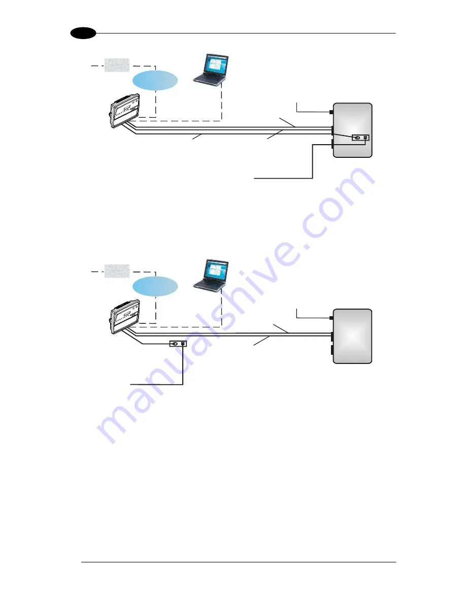
Figure 29 

– Modem Connection through PWO 


Figure 30 

– Modem Connection directly to SC6000 


CAB-SC6003 

Extended I/O 

SC6000 

Power/Net 

CAB-SC6013 

NULL-MODEM 

Cable 

ETHERNET 

VAC INPUT 

PWO 

AUX 

HUB 

to Remote Host 

Telephone line 

CAB-SC6103 

Modem 

CAB-SC6003 

Extended I/O 

SC6000 

Power/Net 

CAB-SC6013 

NULL-MODEM 

Cable 

ETHERNET 

VAC INPUT 

PWO 

AUX 

HUB 

to Remote Host 

Telephone line 

Modem 

Содержание Controller SC6000

Страница 1: ...REFERENCE MANUAL SC6000...

Страница 2: ...r any purpose without the express written permission of Datalogic S p A and or its affiliates Datalogic and the Datalogic logo are registered trademarks of Datalogic S p A in many countries including...

Страница 3: ...erface 15 2 4 6 Profibus Interface 16 2 5 Typical Layouts 17 2 5 1 Large Synchronized Network Layout 17 2 5 2 Redundant System Layout 19 2 5 3 Standard SC6000 to Host Layout 20 2 5 4 SC6000 to Fieldbu...

Страница 4: ...d8K 42 3 4 Parameter Default Values 46 4 MAINTENANCE 51 4 1 Datalogic Automatic Replacement Procedure DARPTM 51 4 2 Automatic Scanner Replacement ASR 52 5 TROUBLESHOOTING 54 6 TECHNICAL FEATURES 56 A...

Страница 5: ...atalogic com and click on the SUPPORT Unattended Scanning Systems category link From this page you can select your product model from the dropdown list which gives you access to Downloads including Da...

Страница 6: ...he compliance of the product with essential requirements listed in the applicable European directive Since the directives and applicable standards are subject to continuous updates and since Datalogic...

Страница 7: ...vii GENERAL VIEW SC6000 Controller Figure A General View Connector Panel Power On and Communication LEDs Connector Panel Legend 1 3 2 LCD Display Programming Keypad Status LEDs 4 6 5 2 3 1 4 5 6...

Страница 8: ...Ethernet Connector 4 Auxiliary Interface Connector 5 Extended I O Connector 6 Figure C SC6000 1211 Profibus Model Connector Panel Profibus Connector 1 Figure D SC6000 1215 DeviceNet Model Connector P...

Страница 9: ...gh the PWO according to the signals Lonworks encoder P S etc necessary for the layout of your application See subparagraphs under par 2 4 and 2 5 See also the PWO Installation Manual 5 Install the Gen...

Страница 10: ...x...

Страница 11: ...ing the onboard Keypad and Display Energy Saving allows allows turning on off the motors and lasers of all network scanners according to the selected digital input encoder or communication channel The...

Страница 12: ...lor State Function Power ON Green ON OFF SC6000 Powered No Power Tx Data Green Blinking OFF Transmitting Data on MAIN No Data Transmission Rx Data Green Blinking OFF Receiving Data on MAIN No Data Rec...

Страница 13: ...to build a reading station based on SC6000 the scanner related accessories are not included Name Description Part Number CAB SC6003 25 pin cable SC6000 to PWO 3m for Extended I O connections 93A051338...

Страница 14: ...the configuration PC NOTE If your system requires the SC6000 to be connected to PWO refer to the Reference Documentation section for details 2 1 PACKAGE CONTENTS Verify that the SC6000 Controller and...

Страница 15: ...re 3 SC6000 Overall Dimensions 180 7 09 309 12 17 5 0 20 N 2 R 1 5 R 0 5 9 15 0 59 50 1 97 48 1 89 N 6 8 0 32 80 3 15 95 3 74 40 1 57 85 3 35 50 1 97 85 3 35 48 1 89 300 11 80 40 1 57 40 1 57 8 0 3 3...

Страница 16: ...rame using the screws and washers Figure 5 Mounting the bracket on the reading station frame 3 Position the SC6000 Controller at the top of the bracket make sure the two large round openings coincide...

Страница 17: ...ce 5 Place a locking washer and then a flat washer onto each knob Tighten the SC6000 Controller to its bracket by screwing the knobs into their holes one on each side Figure 7 Mounting the SC6000 Cont...

Страница 18: ...k 1211 Profibus 9 pin female Profibus network 1215 DeviceNet 5 pin male DeviceNet network 2 4 1 Main Interface The main serial interface is compatible with the following electrical standards RS232 RS4...

Страница 19: ...connector are used for RS232 interface connection Pin Name Function 2 TX Transmit 3 RX Receive 5 GND_ISO Main signal ground 7 CTS Clear to send 8 RTS Request to send The RTS and CTS signals control da...

Страница 20: ...the SC6000 directly to the SC6000 See also par 2 5 1 The following pins of the 9 pin connector are used for RS485 full duplex interface connection Pin Name Function 2 TX485 RS485 output 3 RX485 RS485...

Страница 21: ...SC6000 8 TX485 TX PWO GND ISO 5 RX485 7 RX485 3 RX TX485 2 TX Shield Host Signal Ground RX CAB SC6103 Figure 13 RS485 Full Duplex Interface Connections Using Only TX Signals SC6000 8 TX485 TX GND ISO...

Страница 22: ...ure 15 RS232 Auxiliary Interface Connections 2 4 3 Modem Interface SC6000 offers a dedicated 9 pin port for a Modem connection The modem connection allows a Host to remotely control the reading statio...

Страница 23: ...thernet connections always use the Harting RJ Industrial Push Pull Ethernet connector included in the package This connector assures a robust connection and full IP rated protection Figure 17 Harting...

Страница 24: ...a straight through cable SC6000 5 HUB SWITCH 3 4 2 1 6 5 3 4 2 1 6 7 8 7 8 RX TX TX RX n c n c n c n c n c not connected Figure 18 Straight Through Cable The following is an example of direct connect...

Страница 25: ...eNet connector pinout Pin Name Function 2 V Supply voltage positive pin 5 CAN_L CAN bus data line L 1 SHIELD Shield 4 CAN_H CAN bus data line H 3 V Supply voltage negative pin NOTE The power supplied...

Страница 26: ...N C Not connected 3 B LINE RxD TxD P Received Transmitted data P 4 CNTR P Repeater control signal 5 DGND Data ground M5V 6 5 V Voltage plus P5V 7 N C Not connected 8 A LINE RxD TxD N Received Transmit...

Страница 27: ...the host through one of its interfaces All scanners act as slaves and are connected to the SC6000 through the PWO power supply junction box For DS8100A DX8200A scanners 4 branch connectors provide Lo...

Страница 28: ...der Step 252 OFF ON 1 2 3 4 5 6 7 8 3 For Top Front and Top Back scanners C and D in Figure 23 set the parameter Reading Parameters Reading Condition Skew 45 4 For applications having regular shaped p...

Страница 29: ...ctions as a dedicated protecting or backup unit Figure 24 Redundant Reading Station Layout with DX8200A and DS8100A Scanners AUX CAB SC6103 Extended I O ETHERNET SC6000 CAB SC6003 CAB SC6013 Power Net...

Страница 30: ...irect or through Hub point to point on the Main interface using either RS232 or RS485 full duplex communications to Host directly to a modem for remote Host communications Figure 26 Ethernet Connectio...

Страница 31: ...in Connection directly to SC6000 CAB SC6003 Extended I O SC6000 Main CAB SC6103 NULL MODEM Cable ETHERNET VAC INPUT PWO AUX HUB Host Main CAB SC6013 Power Net CAB SC6003 Extended I O SC6000 Main NULL...

Страница 32: ...SC6000 CAB SC6003 Extended I O SC6000 Power Net CAB SC6013 NULL MODEM Cable ETHERNET VAC INPUT PWO AUX HUB to Remote Host Telephone line CAB SC6103 Modem CAB SC6003 Extended I O SC6000 Power Net CAB S...

Страница 33: ...rnet Connections are made directly through cables to the Fieldbus connector and do not require any converter or adapter Figure 31 Fieldbus Network Figure 32 Dual Ethernet Connection CAB SC6003 Extende...

Страница 34: ...The slave scanners are listed as letters A B C etc or numbers 01 02 03 etc depending on the System Information Section User Interface Style configuration parameter in Genius Above each scanner positi...

Страница 35: ...f the codes enabled on the master R e a d m a s k A B C D E F G H The following indicators are used The node read a barcode enabled on the master space The node read no barcode I O Status Window This...

Страница 36: ...tics Good Read Rate No Read Rate Multiple Read Rate Partial Read Rate calculated on the last 100 codes or in continuous mode depending on the Last Code Reading Mask Window parameter selection Alarms S...

Страница 37: ...t saving or return to the previous branch level Press the Up or Down arrow keys to scroll through a branch list It is possible to access the System menu Setup parameters menu or the PackTrack menu Men...

Страница 38: ...ernet supplementary Ethernet interface only Dual Ethernet models IP addr IP Address GW addr Gateway Address Net mask Netmask MAC addr it is advised not to change this value CFlash Format Format the Co...

Страница 39: ...PackTrack Conditions and Limits The Conditions and Limits for Auto PackTrack Calibration are summarized here for convenience and are also integrated into the following procedure descriptions The follo...

Страница 40: ...t The X Offset moves the Absolute X coordinate X Y Z 0 for all the scanners to the desired point along the X axis which will be measured in step 7 in par 2 7 3 Sensor calibration will be performed eit...

Страница 41: ...not supported by scanner software version U can be calibrated can be calibrated but the calibration procedure fails either barcode reading or verification L Lost scanner stops responding during the pr...

Страница 42: ...of the cluster and then the Continue or Stop screen 6 Repeat steps 3 5 changing the PCT 8000 X position i e always before the PS Line reference point and parallel to a conveyor edge but changing to t...

Страница 43: ...he desired X Offset position and assure that it is read by only one scanner see the figure below After placing the barcode label on the X coordinate you may have to pass your hand or other opaque obje...

Страница 44: ...1077 P1 Z mm 10 P1 Distance mm 36 P1 Position 1077 P2 X mm 715 P2 Y mm 1096 P2 Z mm 10 P2 Distance mm 10 P2 Position 715 P3 X mm 518 P3 Y mm 1304 P3 Z mm 650 P3 Distance mm 1096 P3 Position 10 XP1 X...

Страница 45: ...M Calibrated and verified Scanner N Calibrated and verified Scanner O Calibrated and verified Scanner Q Calibrated and verified Scanner R Calibrated and verified Scanner S Calibrated and verified 2 7...

Страница 46: ...the installation procedure When running Genius the procedure for setting the parameters is supported by a help on line which is displayed in an HTML browser It can be selected from the Configuration H...

Страница 47: ...re 34 Local Device Network Settings The following dialog box appears asking whether to send the updated configuration to the Local Device or not 3 Click the Yes button then click on the icon available...

Страница 48: ...icon in the Device Network area 3 2 1 Genius Network Setup Through Master Network Setup allows configuring your Local Lonworks Network through the Master using Genius Three different procedures are av...

Страница 49: ...the scanner default labels through the Express Network Setup Express Network Setup Before performing this procedure a Lonworks address must be assigned to each slave scanner The most practical method...

Страница 50: ...ocedure of the current network All slave scanners found will be represented in the Current Devices area Then select the desired slave scanner from the Current Devices area and click on the icon or dra...

Страница 51: ...ndicate the scanner corresponding to the one selected in particular in Network Wizard the icon corresponding to the selected slave scanner starts blinking red in the Physical Network all slave scanner...

Страница 52: ...hrough slave scanner keyboard see par Internal Net in the relative Scanner Reference Manual for details 3 3 GUIDE TO RAPID CONFIGURATION FOR SC6000 AS CONTROLLER LON OLD8K This configuration is valid...

Страница 53: ...as shown in the figure below Figure 37 Local Device Network Settings 5 From the Reading System Layout folder and configure the following parameters Device Assignment Controller Lon Old8K Number of Sla...

Страница 54: ...ve Common Parameters branch in the Reading System Layout folder Figure 39 Common Slave Scanner Code Selection Configuration 7 Configure the SC6000 parameters according to your application using the va...

Страница 55: ...ode Definition folder they must be the same as those set for the slave scanners Set up the communication and data formatting parameters in the Data Communications settings folder 8 Send the configurat...

Страница 56: ...ngth 8 Min Code Position 0 Max Code Position 255 CheckDigit Disabled unchecked Pattern Match String 200 char max NULL Code Label Settings 2 Enable Enabled checked Code Symbology Code39 Label Length Va...

Страница 57: ...Data Termination After No Read Message Enabled checked Code Identifier Disabled Standard Parameters Header String STX Code Position Disabled unchecked Code Direction Identifier Enable Disabled uncheck...

Страница 58: ...n by Op Mode Active Closed PSAUX Active Level Overridden by Op Mode Active Closed Input 1 Active Level Overridden by Op Mode Active Closed Input 2 Active Level Overridden by Op Mode Active Closed Inpu...

Страница 59: ...ion Event None Alternative Deactivation Event None Activate on Error Disabled unchecked Deactivate when all Errors Recovered Disabled unchecked Output 5 Use Local Line State Normally Open Activation E...

Страница 60: ...ormally Open Activation Event None Alternative Activation Event None Deactivation Event None Alternative Deactivation Event None Activate on Error Disabled unchecked Deactivate when Errors Recovered D...

Страница 61: ...to move within the menu items 3 In the System menu choose Backup and select the desired backup option complete all scanners controller or each single scanner The SC6000 Controller will store the comp...

Страница 62: ...station is ready to start working again 4 2 AUTOMATIC SCANNER REPLACEMENT ASR When SC6000 is used in a network of DS8100 or DX8200 scanners Topology Role parameter Other Device Assignment parameter C...

Страница 63: ...pact Flash card If a slave scanner has to be replaced the corresponding configuration node address code configuration PackTrack configuration etc is automatically downloaded by the SC6000 into the new...

Страница 64: ...rogram select the OPERATING MODES folder and check for related parameters Serial On Line Mode the reader is not triggered no reading results In the Genius program select the OPERATING MODE folder and...

Страница 65: ...ct corrupted or incomplete In the Genius program select the DATA COMMUNICATION SETTINGS DATA FORMAT folder and check for HEADER TERMINATOR SEPARATOR and FILL CHAR values Check the CODE FIELD LENGTH va...

Страница 66: ...lay 4 lines by 20 characters LCD Keypad 6 keys LED Indicators Power ON TX data RX data Ethernet PS PS Aux TACH Networks Controller Scanners SOFTWARE FEATURES Configuration Modes Genius utility program...

Страница 67: ...or 8 SYS_ENC_I O System signal 9 RES Reserved 10 RES Reserved 11 SHIELD_OUT Lonworks 12 LON_OUT B Lonworks 13 LON_OUT A Lonworks 14 REL2 Relay output control 15 RES Reserved 16 VS Supply voltage 17 EN...

Страница 68: ...12 11 LON A LON B SHIELD USER INTERFACE Figure 42 SC6000 Lonworks Connection PS PS AUX Encoder PS PS AUX ENCODER SC6000 PSIN 5V A B Vext B A V Ground PWO Signal Figure 43 PNP Command Input with Elect...

Страница 69: ...he scanner terminals inside PWO see the PWO Reference Manual for details Figure 45 PNP Command Input Using System Power V PS PS AUX ENCODER Ground SC6000 A B B A GND VS_INPUTS Signal PWO VS VS PSIN 5V...

Страница 70: ...digital output 6 positive pin 13 GND Ground 14 GND Ground 15 IN1 B Input signal 1 polarity insensitive 16 IN2 B Input signal 2 polarity insensitive 17 IN3 B Input signal 3 polarity insensitive 18 GND...

Страница 71: ...e inputs are Maximum voltage 30 V Maximum current 10 mA Outputs Six general purpose outputs are available Pin Name Function 6 OUT 1 Configurable digital output 1 positive pin 19 OUT 1 Configurable dig...

Страница 72: ...In this case however the device is no longer electrically isolated The VS_OUTPUTS on the Extended I O connector is short circuit protected The electrical features of these outputs are Collector emitte...

Страница 73: ...guages Interface A shared boundary defined by common physical interconnection characteristics signal characteristics and meanings of interchanged signals LED Light Emitting Diode A low power electroni...

Страница 74: ...in or 25 pin connector Signal An impulse or fluctuating electrical quantity i e a voltage or current the variations of which represent changes in information Symbol A combination of characters includi...

Страница 75: ...Old8K 42 Guide to Rapid Configuration for SC6000 as Synchronized or Multidata Master 36 I Inputs 60 Installation 4 Interfaces Auxiliary 12 Main RS232 9 Main RS485 Full Duplex 10 K Keypad and Display...

Страница 76: ......

Отзывы: