


INSTALLATION
13
2
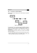
2.5.5
Connection to a Profibus Network
The following figure shows a Profibus layout with C-BOX 3X0 devices connected to a
Profibus Master:
Profibus DP
Slave node #1
PROFIBUS DP
Master
Profibus DP
Slave node #2
Profibus DP
Slave node #n
C-BOX 3X0
Figure 13 - Profibus connection
It is recommended to use only commercially available PROFIBUS connectors for
connecting to the bus. Use connectors from ERNI and Siemens. If the C-BOX is
installed at the beginning or end of the PROFIBUS cable segment, it is
recommended to use PROFIBUS connectors, which contain an integrated
terminating resistor.
To ensure that the C-BOX functions without errors, the shield of the PROFIBUS
cable must be grounded.
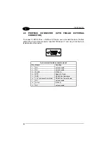
– Ensure that the PROFIBUS connector uses the pin assignments shown in par 2.9.
– Attach the PROFIBUS connector to the PROFIBUS interface socket on the
C-BOX 3X0 and secure the connector with the retaining screws.
Содержание C-BOX 300
Страница 1: ...C BOX 300 310 Installation Manual...
Страница 2: ...C BOX 300 310 Installation Manual...
Страница 3: ...C BOX 300 310 INSTALLATION MANUAL...
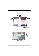
Страница 8: ...vi C BOX 310 1 2 Figure B LCD display Keypad 1 2...
Страница 11: ...ix C BOX 310 Figure D Bottom inside...
Страница 14: ...xii...


