background image

DM4170 – Installation Manual 

Installing the DM4170 


204.4308.03 

23 


The DM4170 has a label on the rear side of the


mechanics. It contains


model information, 

product  code  and  serial  number.  Check  if  there  is  any  divergent  information


on  the  label 

regarding the information on the packaging.  


19-

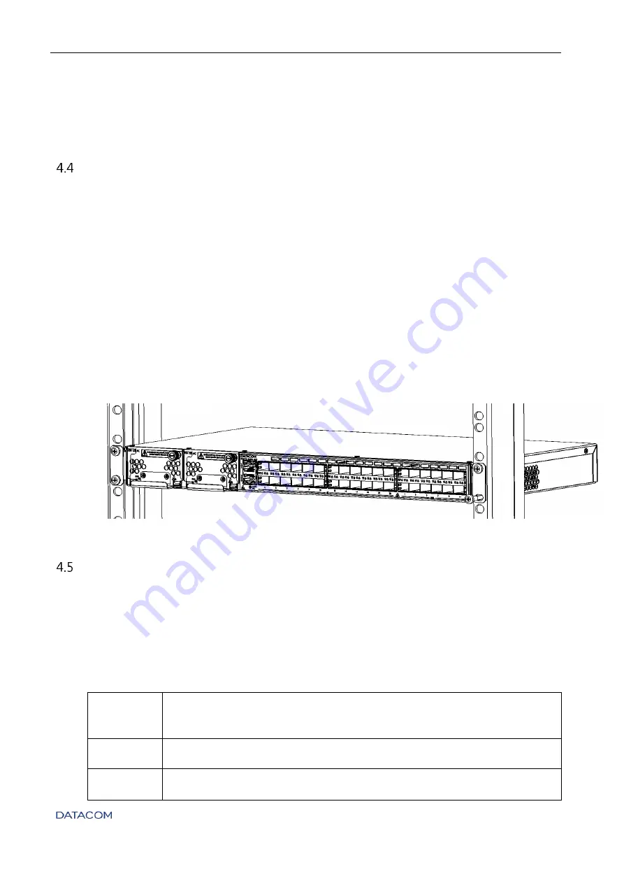
INCH RACK INSTALLATION


The DM4170 was designed to be installed to 19-inch racks,


occupying only 1U in height. To 

choose the suitable installation site, pay attention to the following items: 


Choose an easily accessible location where your LEDs can be viewed; 


The  temperature  should  be  between  0°C  and  55°C  and  the  relative  air  humidity 
should be between 10% and 90% non-condensed; 


Install the equipment near a power source.  


After  choosing  the  appropriate  location,  bring  the  equipment  to  the  rack  and  insert  two 
standard M5 screws (not shipped with the product) into each side of the adapter to secure 
the assembly to the cage nuts on


the rack (not shipped with the product). Finally,


tighten the 

screws so as to guarantee that the equipment is securely attached to the rack. 


Figure 19 - 19-inch rack installation 


C

ONNECTING THE 

PROTECTIVE


GROUNDING 

The  DM4170  has  a  place  on  its  rear  panel  to  attach  a  cable  to  connect  the  Protective 
Grounding. 

The grounding cable is not part of the basic accessories shipped with the switch. The cable 
indicated for the installation must have a thickness of 10 to 12 AWG. The color of the cable 
must follow the specific requirements of the country where the switch will be installed; most 
countries determine that the cable should be green with yellow stripes.  

Step 1 

• 

Locate  the  grounding  connector  located  on  the  back  of  the  switch  as 
shown  in 

F

IGURE 

18


P

ROTECTIVE 

G

ROUNDING  IN

  DM4170


Protective 

Grounding; remove the connector with a Philips screwdriver.   

Step 2 

• 

Secure the cable to the grounding connector. 

Step 3 

• 

Cut the cable to a length suitable for the connection to the installation 
ground. 

Содержание DM4170 Series

Страница 1: ...INSTALLATION MANUAL CARRIER ETHERNET SWITCH 204 4308 03 DM4170...

Страница 2: ...ACOM All Rights Reserved WARRANTY This product is guaranteed against material and manufacturing defects for the period specified in the sales invoice The warranty only includes the repair and replacem...

Страница 3: ...e of the equipment in addition to providing technical assistance for repairs and maintenance Email suporte datacom ind br Phone 55 51 3933 3122 Website http www datacom ind br en support GENERAL INFOR...

Страница 4: ...the products English only Installation Manual Provides orientation about product installation procedures Quick Reference Guide Provides summarized instructions for the product s installation and conf...

Страница 5: ...70 24GX 12XS 10 DM4170 24GX 4XS 2QX 11 EQUIPMENT STATUS LEDS 11 SERIAL CONSOLE INTERFACE RS 232 12 USB INTERFACE CONSOLE 13 USB HOST INTERFACE 13 ETHERNET MANAGEMENT INTERFACE MGMT 13 DATA INTERFACES...

Страница 6: ...SU 125 24 4 7 2 Connecting to Power Supply 25 CHECKING THE PRODUCT S OPERATION 25 5 INSTALLING AND REMOVING SFP SFP QSFP MODULES 26 INSTALLING SFP SFP MODULES 27 REMOVING SFP SFP MODULES 28 6 ACCESSIN...

Страница 7: ...his formatting indicates that the text contained herein is of great importance and there is a risk of damage Warning Indicates that if the procedures are not followed correctly there is a risk of elec...

Страница 8: ...e calls attention to conditions that if not avoided can result in death or serious injury 1 3 2 Texts Convention Description Hyperlink Indicates an Internet site or e mail address It can also be used...

Страница 9: ...med by qualified and trained personnel authorized to carry out such tasks To prevent the risk of electric shocks before connecting the equipment or connecting cables ensure the installation and operat...

Страница 10: ...B Host Interface 4 Serial Console Interface RS 232 5 Gigabit Ethernet Management Interface MGMT 6 LED Power PWR 7 LED ALARM FAIL 8 24 Gigabit Ethernet Ports SFP 9 12 10Gigabit Ethernet Ports SFP 10 Fr...

Страница 11: ...gabit Ethernet Ports SFP 10 2 40Gigabit Ethernet Ports QSFP 11 Front Panel Air Entry 12 Rear Panel Air Exit 13 Auxiliary Safety Ground 14 USB Storage Interface 15 Alarm Interface 2 inputs and 1 output...

Страница 12: ...switch has a console port for local management The console port uses an RJ45 connector A cable with a male RJ45 connector and a female DB9 connector must be used for the connection to a computer or l...

Страница 13: ...ort is recognized and emulated as a serial port this port can be accessed via a serial connection program DATACOM does not provide the driver that will emulate or create a virtual serial port from the...

Страница 14: ...connectors corresponding to each interface The ports are identified in the front panel s printing but only odd ports bottom ports are numbered The numbering of the other ports follows the order accord...

Страница 15: ...GbE SFP LED ports 3 8 2 1 Indicator LEDs of the 10 Gigabit Ethernet optical interfaces The convention to indicate the operation and mode of operation of the 10GbE SFP interfaces is described in TABLE...

Страница 16: ...ink Up at 40Gbps active port On YELLOW Link Up operating at a rate lower than 40Gbps Blinking Data sending and or receiving activity Table 10 Indicator LEDs of 40GbE QSFP interfaces ALARM INPUT AND OU...

Страница 17: ...60 Vdc power supply and the PSU 125 AC that operates with 100 240Vac 50 60Hz AC power supply For further details read the TECHNICAL SPECIFICATIONS chapter The PSU 125 DC has TERMINAL BLOCK power termi...

Страница 18: ...ations The F3 output fuse supports currents up to 15A It is also 86V Fast Acting If necessary also replace it with another one with the same specifications In the PSU 125 AC fuse F1 supports currents...

Страница 19: ...C 320 C14 connector for the power supply of the equipment Figure 13 AC Power Connector Pin Assignment According to the NBR 14136 standard the grounding pin of the product must be connected to the grou...

Страница 20: ...or normally shipped screwed to the PSU 125 DC for the installation of the cable Follow the information below to install the cable to the Terminal Block connector Step 1 Remove the TERMINAL BLOCK conne...

Страница 21: ...nector with the cable installed on the PSU 125 DC using the same 1 8 screwdriver number 0 used above as shown below Figure 17 Installing the cable mounted to the TERMINAL BLOCK on the PSU 125 DC Table...

Страница 22: ...1 2 Environment requirements Electrical equipment can generate significant heat Thus it is essential to provide a temperature controlled environment to ensure proper and safe operation In addition to...

Страница 23: ...ide of the adapter to secure the assembly to the cage nuts on the rack not shipped with the product Finally tighten the screws so as to guarantee that the equipment is securely attached to the rack Fi...

Страница 24: ...ar panel and on the left side of the switch These areas must have free air circulation so that the temperature of the equipment remains within the assured levels of operation also observing the coolin...

Страница 25: ...Step 1 Immediately after the unit is powered by either of the power inputs the power on PSU PWR indicator will light up After approximately 3 seconds the switch s PWR LED will light up followed by a b...

Страница 26: ...amage to the cords Care with Optical Modules o When handling the optical modules you need to always use an antistatic wrist strap o In order to transport and store the optical modules it is necessary...

Страница 27: ...FP SFP into the cage Step 3 After inserting the module it is necessary to lock it by moving the safety latch This latch also serves to lock the optical cord after they are inserted Safety Latch Figure...

Страница 28: ...ion later In order to remove the modules simply follow the same insertion instructions in reverse order Step 1 Remove the optical cords Step 2 Lower the safety latch Step 3 Pull the module by its safe...

Страница 29: ...170 switch does not support hardware flow control In the configuration of the console port the hardware flow control should be disabled MANAGEMENT THROUGH THE ETHERNET OUTBAND INTERFACE MGMT In the fa...

Страница 30: ...emulator After pressing Enter you should see the following message requesting your login DM4170 login Step 2 The equipment s factory default user password pair is admin admin Enter user admin and pre...

Страница 31: ...1 100Base Fx 1000Base X SFP 24 10 100 1000Base T RJ45 1000Base X 10GBase X SFP 12 4 40GBase X QSFP 2 Table 20 Interfaces DM4170 POWER SUPPLY SPECIFICATIONS PSU 125 AC PSU 125 DC Rated operating voltag...

Страница 32: ...HYSICAL SPECIFICATIONS DM4170 24GX 12XS DM4170 24GX 4XS 2QX Height 42 5 mm 42 5 mm Width with Brackets 482 mm 482 mm Width without Brackets 444 mm 444 mm Depth 209 2 mm 209 2 mm Weight 3 580 kg 3 400...

Отзывы: