43
When the address of the controller is fixed at 0
The addresses of the peripheral devices are 1, 2, 3… in order, starting from the one nearest the
controller. The address of the peripheral device is set by sending address commands during the
initialization of the network.
When the address of the controller is fixed at 1 through 7
The addresses of the peripheral devices will be set on a pre-selected number. Within a single system,
the same number can be used only once. If an address-switch number other than 0 is to be used,
change the PTC-150 address switch to a different number beforehand.
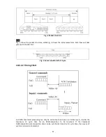
Each VISCA device has a VISCA IN and VISCA OUT connector.
Set the DTR input (the S output of the controller) of VISCA IN to H when controlling VISCA
equipment from the controller.
Fig. 1 VISCA network configuration
10.2.2 VISCA Communication Specifications
10.2.2.1 VISCA Packet Structure
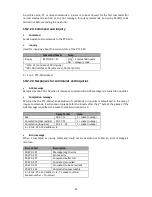
The basic unit of VISCA communication is called a packet (Fig. 2). The first byte of the packet is
called the header and comprises the sender’s and receiver’s addresses. For example, the header
of the packet sent to the PTC-150 assigned address 1 from the controller (address 0) is
hexadecimal 81H. The packet sent to the PTC-150 assigned address 2 is 82H. In the command list,
as the header is 8X, input the address of the PTC-150 at X. The header of the reply packet from
the PTC-150 assigned address 1 is 90H. The packet from the PTC-150 assigned address 2 is A0H.
Some of the commands for setting PTC-150 units can be sent to all devices at one time
(broadcast). In the case of broadcast, the header should be hexadecimal 88H.
When the terminator is FFH, it signifies the end of the packet.
VISCA Equipment
VISCA Controller
IN
OUT
Содержание PTC-150T
Страница 1: ...1 ...
Страница 9: ...9 5 System Diagram ...
Страница 24: ...24 ...
Страница 25: ...25 7 5 Step 5 Mount Camera to Ceiling ...
Страница 53: ...53 12 Dimensions Unit mm ...
Страница 54: ...54 ...
Страница 57: ...57 14 Service and Support ...


