Chapter 2
14
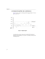
An Example Using Offset, Gain, and Reference
shows a signal in which part of the image is below 0.0 V and
part is above 1.0 V.
Figure 3: Original Signal
To adjust the black and white levels so that the DT3152-LS board
digitizes the signal between
−
0.4 V and 1.1 V, perform the steps in the
following sections.
−
0.5 V
0 V
0.5 V
1.0 V
1.5 V
2.0 V
Offset = 0
Gain = 1
Reference= 1
Содержание DT3152-LS
Страница 1: ...MACH Series UM 16481 F DT3152 LS User s Manual ...
Страница 4: ......
Страница 16: ...About this Manual xvi ...
Страница 17: ...1 1 Overview Features 2 Supported Software 4 Accessories 6 ...
Страница 142: ...Chapter 4 126 ...
Страница 143: ...127 5 Troubleshooting General Checklist 128 Service and Support 132 If Your Board Needs Factory Service 136 ...
Страница 153: ...137 A Specifications ...
Страница 156: ...Appendix A 140 ...
Страница 157: ...141 B Connector Pin Assignments Connector J1 Pin Assignments 142 Connector J2 Pin Assignments 144 ...
Страница 162: ...Appendix B 146 ...
Страница 192: ...Appendix C 176 ...
Страница 193: ...177 D Asynchronous Reset Cameras ...
Страница 196: ...Appendix D 180 ...
Страница 210: ......
Страница 214: ......


