background image


27 

7.5 Fitting the light head 


NOTE: The arm will not balance until the head is fitted  


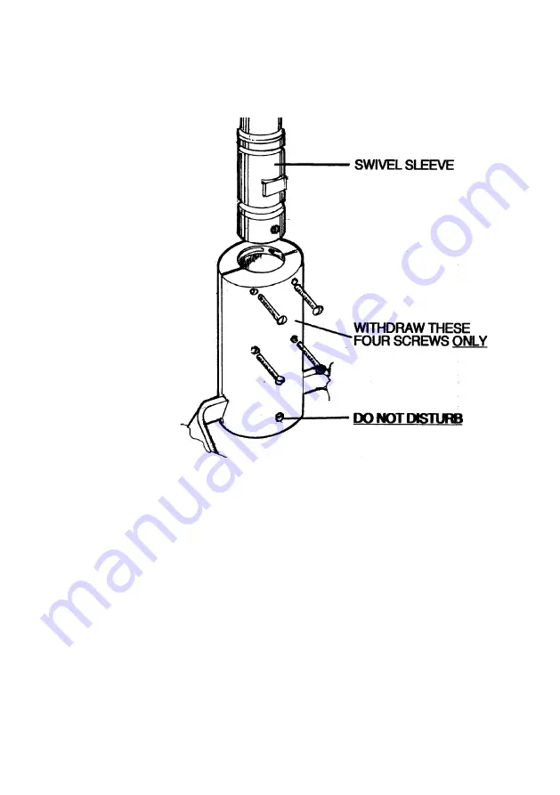
Remove four M3 screws, as shown, from the slip ring housing. Make sure the bottom fifth 

screw is left in place. 


Note: the four M3 screws may be supplied separately in a plastic bag with the warranty 

card. 


Ease the 2 halves of the slip ring housing open slightly and slide the lamp-head unit up over 

the swivel sleeve until the top face meets the lower face of the anchor block, ensuring that 

the flat on the swivel sleeve is positioned as shown. 


Replace the four M3 screws so that they engage the slots in the swivel sleeve. Do not over-

tighten the screws. 


Check everything for tightness and safety. 


Check the arm and head for freedom of movement. 


Rebalance the jib arm, if necessary, as described above. 


Provide power to the power-supply module and switch on the green rocker switch which 

Содержание BILITE

Страница 1: ... BILITE UNIT CEILING AND WALL MOUNTED OPERATING AND INSTALLATION MANUAL QAM BILITE 0811 7 ...

Страница 2: ......

Страница 3: ...hooting 8 4 2 Routine maintenance 9 5 LAMP BAR REPLACEMENT 10 6 ADJUSTMENT OF ARM BALANCE TO ELIMINATE DRIFT 11 7 INSTALLATION 12 7 1 Unit chair mount with remote transformer 12 7 2 Ceiling mount 13 7 3 Wall mount 19 7 4 Installation Fit the jib joint cover 21 7 5 Fitting the light head 22 RETURNS POLICY 24 WARRANTY 25 WARRANTY REGISTRATION 26 Tel 0844 375 9000 Fax 0333 321 0973 ...

Страница 4: ...4 info daray com www daray com ...

Страница 5: ...rm and the light head The power supply module is fitted with an IEC inlet so the mains may be supplied via a plug in flex from a standard mains socket This arrangement can readily be converted using a parts kit supplied as standard for use where the mains electrical supply cables are chased into a wall The power supply module is fastened to the wall mount bracket for the BLLW and can be screwed to...

Страница 6: ...6 2 2 Dimensions 1 2 ...

Страница 7: ...7 ...

Страница 8: ...8 Dimensions 2 2 ...

Страница 9: ...nt Switch on at the switch fused spur The indicator on the switch fused spur should illuminate Turn on the light using the switch on the head mounting Set the required illumination level using the variable intensity control module If the Bilite does not illuminate press the variable intensity control knob and then set the desired intensity All models After use switch off the power supply module on...

Страница 10: ...o all surfaces a 1 solution of sodium hypochlorite using a soft cloth Within 10 minutes remove the chemical from all surfaces using a damp soft cloth The chemical will cause corrosion of metal parts if it is not thoroughly removed Apply Isopranol to the surfaces this is an alcohol based fluid which evaporates without leaving any residue and can be obtained as an impregnated cloth applicator 4 1 Tr...

Страница 11: ...ing the fitting adaptor into the down tube Lower the arm until the adaptor and key can be removed Slide sleeve up and inspect for lubrication Re lubricate spigot and sleeve if required Reassemble Check tightness of all five fixing screws One month after installation and then annually Check balance of jib over whole range See section 6 Ceiling Mount Operation Suggested Interval Method Inspect 6 but...

Страница 12: ... the lugs at each end The lamp bar may then be withdrawn from the case CAUTION the lamp will be very hot if the light has been recently used Being careful not to touch the bulb itself fit a new lamp bar by engaging its 2 prongs into the guide holes and pushing evenly home Remember to order spare lamp bars LB1024 ...

Страница 13: ...in the opposite direction to Arrow A To assist in making this adjustment it may be necessary to remove the arm joint cover Remove the 2 snap in plugs and the 2 screws allowing the cover half mouldings to be separated and the moving cover to slide down the jib arm This provides better access to the slot through which the capstan nut is adjusted Note When re assembling ensure that the moving cover i...

Страница 14: ...olex adaptors at either end one which will connect to the transformer only the other to the Molex adaptor on the low voltage cable supply of the arm assembly Feed the low voltage cable through the support post and any umbilical to the transformer site Make sure there are no sharp bends or possible contact with surfaces which may rub or cut the cable Remote transformer Low voltage cable Support pos...

Страница 15: ...ount the light WARNING please note that this information is provided for guidance only and that a qualified builder or structural engineer should be consulted if you have any doubt about the suitability of the proposed mounting position WARNING the light head operates from a low voltage supply produced by a transformer in the ceiling mount assembly and fed through the suspension arm On NO ACCOUNT ...

Страница 16: ...g with bolts screws or studs and nuts through the centre of each jack bolt Do not fully tighten the fasteners at this point Note The nuts thread locked to the upper end of the 3 jack bolts act as pressure pads These pressure pads must be seated firmly against the mounting surface The jack bolts can then be used to adjust the position of the ceiling plate and down tube ...

Страница 17: ...amp bolts Fit the down tube in the clamp and tighten the clamp bolts to firmly hold it in place Drill a 6mm hole completely through the tube via the guide holes in the clamp and fit the safety bolt and nylon insert lock nut supplied NOTE TO ENSURE THE USER S SAFETY THE SAFETY BOLT AND NYLON INSERT LOCK NUT MUST BE FITTED PROPERLY Feed the end of the low voltage cable assembly through the tube Tigh...

Страница 18: ...he cover holding it in place with the retaining band from the fitting kit Install the primary arm To ensure the smooth rotation of the arm it is essential that the primary arm spigot is lightly lubricated before assembly A sachet of silicon grease is provided Place the nylon washer over the primary arm spigot Insert the primary arm spigot into the down tube Down tube Arm assembly Nylon washer Conn...

Страница 19: ...Make sure to sit the joined connectors inside the bung before fitting to prevent the cable from being damaged Fit the jib joint cover see p 20 Fit the light head see p 21 Check everything for tightness and safety Check the arm and head for freedom of movement Rebalance the jib arm if necessary see p 11 ...

Страница 20: ...20 ...

Страница 21: ... module via a switched fused spur Run a 1 5mm2 twin and earth cable to the ceiling plate 230V terminal block Provide power to the power supply module and switch on the green rocker switch which should illuminate Turn on the light with the rocker switch on its mounting swivel and check that the light illuminates and that the variable intensity control module works Ceiling mounted Bilite wiring diag...

Страница 22: ... of the bracket into which the primary arm fits should be 1696 mm above the floor WARNING If in doubt consult a building engineer Secure the plate to the wall ensuring that it is truly vertical WARNING the light head operates from a low voltage supply produced by a transformer in the power supply module and fed through the suspension arm On NO ACCOUNT should the arm be connected directly to mains ...

Страница 23: ...cable from the primary arm through the top of the power supply module Connect the low voltage cable to the 2 way terminal block wired to the low voltage output from the transformer The power supply module requires an earthed mains electrical supply either fed into its rear or into a socket on the side depending on the module supplied Connect the incoming mains cable to the 3 way LEN terminal block...

Страница 24: ...arm and head for freedom of movement Rebalance the jib arm if necessary see p 11 Provide power to the power supply module and check that the mains indicator illuminates Operate the variable intensity control module by pressing it Rotate to dim Check that the light head illuminates and that the intensity control works ...

Страница 25: ...ider with its T mark uppermost into the groove inside the cover 2 Align holes in cover and painted elbow Nip up the screw to secure DO NOT OVERTIGHTEN 3 Fit opposite cover DO NOT OVERTIGHTEN Fit a plug in each hole 4 Carefully check the operation of arm and the jib joint cover Locating key CUT OUT in aluminium casting Slider Fixing hole ...

Страница 26: ...26 ...

Страница 27: ...en slightly and slide the lamp head unit up over the swivel sleeve until the top face meets the lower face of the anchor block ensuring that the flat on the swivel sleeve is positioned as shown Replace the four M3 screws so that they engage the slots in the swivel sleeve Do not over tighten the screws Check everything for tightness and safety Check the arm and head for freedom of movement Rebalanc...

Страница 28: ...rocker switch on its mounting swivel Check that the light illuminates and that the dimmer control works As necessary realign the overlap of the 2 rectangular light patches by turning the adjusters on the rear of the light head using the tool provided ...

Страница 29: ...ion which is not covered by the above We will try to help but we cannot normally offer a refund DOA dead on arrival For additional clarification please refer to our terms and conditions at www daray co uk terms In a small number of cases we may determine that a replacement would not work any better than the original product we supplied In such cases we will only offer a refund rather than a replac...

Страница 30: ...ARAY s instructions Attachment of fittings and accessories not approved by DARAY Repairs modifications carried out by service personnel not approved by DARAY Damage caused by chemical corrosion from cleaning agents not approved by DARAY Failure to use or install the product in accordance with the manufacturer s instructions 5 Nothing in this warranty shall have the effect of restricting or excludi...

Страница 31: ...RCHASED FROM PRODUCT SERIAL No ALTERNATIVELY REGISTER ONLINE AT WWW DARAY COM Freepost Plus RRAS YGXE SLBC Daray Ltd Marquis Drive SWADLINCOTE DE12 6EJ 3 YEAR AFTERCARE PLAN Occasionally DARAY would like to send you information about our special offers and promotions If you do not wish to receive such information please tick here Privacy statement DARAY will not pass on your details to any third p...

Страница 32: ......

Страница 33: ...Marquis Drive Moira Derbyshire DE12 6EJ Tel 0844 375 9000 Fax 0333 321 0973 info daray co uk www daray co uk ...

Отзывы: