8
IMIX 7.3
Ordercode: D2351
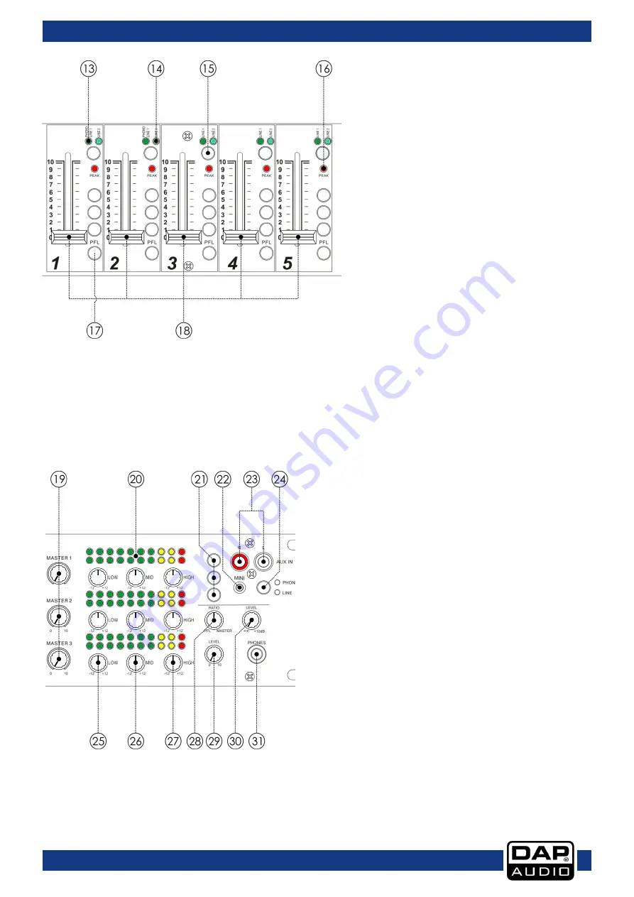
13. Phono-line 1 LED
Indicates that the phono-line 1 input is
selected.
14. Line 2 LED
Indicates that the line 2 input is selected.
15. Selection button (phono-line 1/line 2)
With this switch you can choose between two
sets of inputs per channel.
16. Peak LED
The peak LED shows signal peaks in a
channel’s incoming signal. If the red peak LED
frequently blinks or constantly lights, the
corresponding channel is likely to enter
clipping and you have to reduce the input’s
amplification using the corresponding gain
(38-42) control on the back. The peak LED
lights at a level of 8 dB below clipping. Make
sure that the peak LED lights only briefly during
dynamic peaks.
17. PFL button
The PFL button (pre fade listening) is designed to route the channel input to the monitor section
independent of the individual channel’s volume fader setting. It is possible to assign more than one
channel simultaneous to the PFL bus.
18. Channel fader
A logarithmic 50mm fader, which controls the volume of the corresponding channel. The overall volume
is set with the master control.
19. Master control (master 1-3)
You can adjust the output signal to the
master 1-3
outputs (48-52).
20. Output signal VU-meter (master 1-3)
This meter is a multi-step LED. The accurate level
indication allows you to monitor the output signal
level at anytime, and match with other devices.
21. Zone select buttons
Use these 3 buttons to assign the channel to 1 or more
master outputs.
22. Aux mini jack in connector
Unbalanced stereo mini jack aux input for connecting
a line/phones level device. Use the Phone/Line ()
switch to set up this input for connecting either
headphone or line level output devices.
23. Aux RCA in connectors
Unbalanced stereo RCA aux input for connecting a
line/phones level device. Use the
phone/line (24)
button to set up this input for connecting either
headphone or line level output devices.
Содержание IMIX-7.3
Страница 15: ...14 IMIX 7 3 Ordercode D2351 Block diagram...
Страница 16: ...2013 DAP Audio...


