background image


16 


GIG-124C 

Order code: D2284  

42. AC INLET WITH FUSE HOLDER


Before connecting the unit to the mains, ensure that the voltage setting 
matches your local voltage. Blown fuses should only be replaced by 
fuses of the same type and rating. To disconnect the unit from the 
mains, pull out the main cord plug. 
 

43. POWER ON / OFF


Use the POWER switch to turn on the mixing console. The POWER switch 
should  always be in the “Off” position when you are about to connect 
your unit to the mains. 
 

44. PHANTOM ON / OFF


Phantom power is used for operating a capacitor microphone. As a 
rule, dynamic microphones can still be used with phantom power, 
provided they are wired in a balanced configuration. 


Installation and connection 

 
At this point you are in a position to successfully operate your GIG-124C Mixing Console. However, we 
advise you to carefully read the following section to be a real master of your own mixer. Not paying 
enough attention to the input signal level, to the routing of the signal and the assignment of the signal will 
result in unwanted distortion, a corrupted signal or no sound at all. So you should follow these procedures 
for every single channel: 


Before connecting mics or instruments, make sure that the power of all your system components, 
including the mixer, are turned off. Also, make sure that all the input and output controls are 
turned down. This will avoid damage to your speakers and avoid excessive noise. 


Properly connect all external devices such as mics, power amplifiers, speakers, effect processor 
etc. 


Now, turn on the power of any peripheral devices, then power up the mixer. 


Set the output level of your mixer or the connected power amplifier at no more than 75%. 


Set the CONTROL ROOM/PHONE level at no more than 50%. 


Position HI, MID and LOW EQ controls on middle position. 


Position panoramic (PAN/BAL) control on center position. 


While speaking into the mic (or playing the instrument), adjust the channel Level control so that 
the PEAK LED will blink occasionally, in this way you will maintain good headroom and dynamic 
range. 


You can shape the tone of each channel by adjusting the equalizer controls as desired. 


Now repeat the same sequence for all the input channels. The main LEDs can move up into the 
red section, in this case you can adjust the overall output level through the MAIN MIX control. 


Содержание GIG-124C

Страница 1: ...GIG 124C Highlite International B V Vestastraat 2 6468 EX Kerkrade the Netherlands Order code D2284 MANUAL ENGLISH...

Страница 2: ...on of the device 5 Features 5 Overview 5 Installation 6 Introduction 6 Ready to start 6 Control Elements 7 Modules 12 Option One SMP S Order code D2290 12 Option Two SMP R Order code D2291 14 Option T...

Страница 3: ...uld there be any consult your dealer and do not use the system To maintain perfect condition and to ensure a safe operation it is absolutely necessary for the user to follow the safety instructions an...

Страница 4: ...and the power cord from time to time Please turn off the power switch when changing the power cord or signal cable or select the input mode switch Extreme frequency boosts in connection with a high i...

Страница 5: ...he customer s responsibility Highlite reserves the right to use its own discretion to repair or replace product s As a suggestion proper UPS packing or double boxing is always a safe method to use Not...

Страница 6: ...band EQ and Peak LEDs on each MIC channel 2 band EQ and Peak LEDs on Stereo channels 1 AUX Sends POST PRE per channel for monitoring or external effects 1 AUX Sends POST Fader for monitoring or extern...

Страница 7: ...ck inputs assignable to main mix control room phones Outputs etc This unit is very easy to operate but we advise you to go through each section of this manual carefully Ready to start 1 Please check t...

Страница 8: ...ssors Here you can hook up a compressor noise gate or equalizer to process the signal of a single channel The insert jack is placed before the fader EQ and aux send Please use an insert cable to conne...

Страница 9: ...ader to pre fader This way the volume level of the aux signal is not affected by the channel fader 12 AUX 2 POST The aux buses are used as additional flexible send paths for various applications The A...

Страница 10: ...switch the 2 TRACK IN signal will be routed to the CONTROL ROOM output Push the switch again the 2TRACK IN signal will be routed into the MAIN MIX output 23 2 TK IN MP3 This control allows you to adj...

Страница 11: ...are used to hook up CD players tape decks or other line level sources TAPE OUT The CD TAPE output connectors provide the stereo main mix signal to a tape deck or DAT recorder to record your mix 34 MAI...

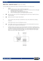
Страница 12: ...to the user s requirements Open the cover and connect the module to connector CN6 The optional modules are SMP R SMP S Bluetooth 2 1 The signal for module playback can be assigned to Main Mix by 2TK...

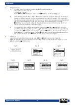
Страница 13: ...hows Searching At the end of the search the display will show the menu as shown in Fig 02 see next page Using PRE NEXT keys you can select one of following three menu options Playing Program and Folde...

Страница 14: ...the STOP key you will return to Fig 02 The play list can accept up to 20 songs and it will display the list according to song insert order 3 The display will show the following interface Press the PR...

Страница 15: ...mbol on the screen is Repeat Repeats a single track several times the symbol on the screen is Play in order play all the tracks in order the symbol on the screen is blank Random play All tracks will b...

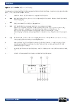
Страница 16: ...ct a previous track for playing C NEXT Use this button to skip to the next track D VOL Press the VOL button key to decrease the volume The default factory setting is maximum E VOL Press the VOL button...

Страница 17: ...pted signal or no sound at all So you should follow these procedures for every single channel Before connecting mics or instruments make sure that the power of all your system components including the...

Страница 18: ...eliability Periodically check your cables A great number of problems faulty contacts ground hum discharges etc are caused entirely by using unsuitable or faulty cables Headphone Unbalanced Balanced Fo...

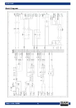
Страница 19: ...18 GIG 124C Order code D2284 Block Diagram...

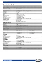
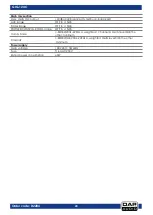
Страница 20: ...c input XLR balanced LOW CUT 100Hz Line input 1 4 TRS or TRS RCA un balanced Frequency response 10Hz to 55KHz 3dB Distortion THD N 0 03 at 0dB 22Hz 22KHz A weighted Sensitivity range 20dBu 20dBu SNR 1...

Страница 21: ...F to 15dB Fader range OFF to 10dB PHONES CONTROL ROOM range OFF to 15dB Hum Noise 80dB 20Hz 22KHz A weighted 1 channel MAIN level 0dB the other minimum Crosstalk 80dB 0dB 20Hz 22KHz A weighted MAIN le...

Страница 22: ...21 GIG 124C Order code D2284 Notes...

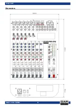
Страница 23: ...22 GIG 124C Order code D2284 Dimensions...

Страница 24: ...2013 DAP Audio...

Отзывы: