Dantel 46034 Скачать руководство пользователя страница 16

P

AGE

 16

46034-0997 <90-00030>

OPERATION

O

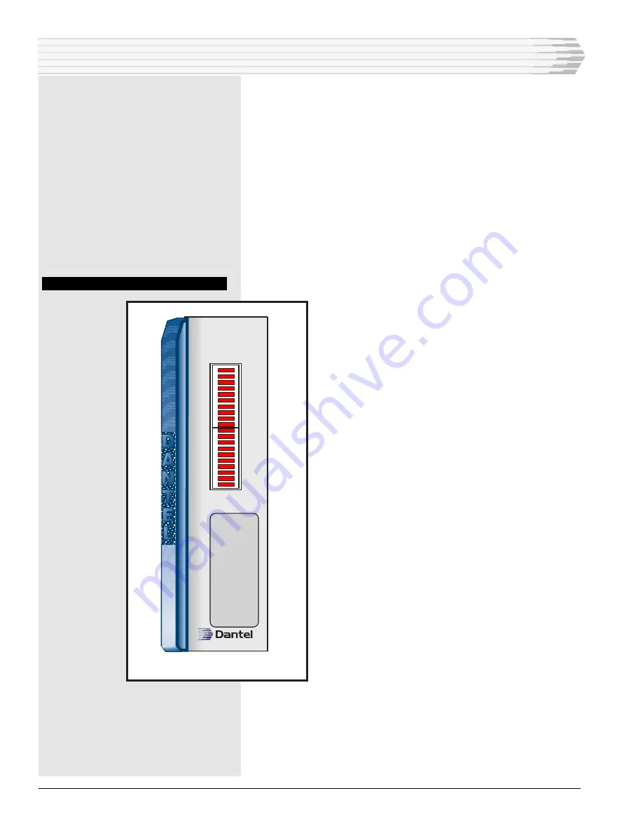
peration of the 46034 Hubbing Module consists of observing

the 20 front panel LEDs that indicate the activity of all 9

ports. Refer to Fig. 9.
The first eight LEDs, labeled RX1 to RX8 respectively, indicate

receive (RX) activity for data ports one through eight.
The next eight LEDs, labeled TX1 to TX8 respectively, indicate

transmit (TX) activity for data ports one through eight.
The next two LEDs are not labeled and do not function.
The last two LEDs, labeled RXD and TXD, indicate data trans-

mit (TXD) and data receive (RXD) activity for the communica-

tions subassembly (port nine).

F

IG

. 9 - 46034 F

RONT

 P

ANEL

 V

IEW

46034-00 REV__

46034-00

HUBBING

MODULE

RX  1

RX  2

RX  3

RX  4

RX  5

RX  6

RX  7

RX  8

TX  1

TX  2

TX  3

TX  4

TX  5

TX  6

TX  7

TX  8

RXD

TXD

Содержание 46034

Страница 1: ...recautions refer to BellcoreTM Technical Reference TR NWT 000870 Copyright 1997 by Dantel Inc Dantel is a registered trademark of Dantel Inc ISO 9001 Registered Printed in the U S A INSTALLATION OPERA...

Страница 2: ...e operating with a 49029 RS 232 Current Loop Interface Subassembly The module comes with a TTL subassembly bypass card that allows port nine to function as a TTL data bus interface in the absence of a...

Страница 3: ...s the front panel TX LED The ninth data port provides a mounting for installing various communication subassemblies With the five six lever DIP switches the port supports the following interfaces TTL...

Страница 4: ...S 422 Output Data Port 5 VDC TDX 5 VDC TX CA RX RX CF 54 53 36 56 55 18 RXD TXD CTS RTS DCD DTR DSR 1 2 Strap D Strap C 2 5 VDC 12 VDC 12 VDC RXD TXD CTS RTS DCD 39 41 43 42 40 21 to 56 VDC 35 17 TTL...

Страница 5: ...22 TX Pin 1 Pin 5 Pin 9 Pin 13 Pin 19 Pin 23 Pin 27 Pin 31 RS 422 RX Pin 3 Pin 7 Pin 11 Pin 15 Pin 21 Pin 25 Pin 29 Pin 33 RS 422 RX Pin 4 Pin 8 Pin 12 Pin 16 Pin 22 Pin 26 Pin 30 Pin 34 TABLE B PC PI...

Страница 6: ...ce Note Use each of the six buses carrying data between the data communication ports for one data polling system only If more than one alarm polling system s data routes to a bus the system does not f...

Страница 7: ...ridging between data ports in different modules BRIDGING APPLICATIONS Fig 4 shows a switch setting diagram for bridging applications using half duplex communication Each data port on the data bridge m...

Страница 8: ...8 45 46 A B C D E F REF 7 8 3 2 1 5 VDC RX1 S22 7 TX1 1 2 6 5 Strap 1B 8B REF 11 12 3 2 1 5 VDC RX1 S22 6 TX1 1 2 10 9 Strap 1B 8B REF 3 4 3 2 1 5 VDC RX1 S22 8 TX1 1 2 2 1 Strap 1B 8B DATA DATA DATA...

Страница 9: ...Switch S10 1 On All Switches Off 49 50 47 48 45 46 A B C D E F REF 7 8 3 2 1 5 VDC RX1 S22 7 TX1 1 2 6 5 Strap 1B 8B 3 4 3 2 1 5 VDC RX1 S22 8 TX1 1 2 2 1 Strap 1B 8B RS 232 RS 422 RS 232 RS 422 REF R...

Страница 10: ...TX BA CF CA To External Equipment TTL PORT DATA DATA DATA DATA DATA DATA 5 VDC Buses A F To Other Data Ports Data Port 1 RS232 Strap 1A 8A Data Port 2 RS 232 Strap 1A 8A Unused Two ports are required...

Страница 11: ...onnections If a TTL subassembly bypass card was installed remove the blue hole plug from the front panel subassembly window Install the new subassembly Refer to Fig 6 Ensure the subas sembly connector...

Страница 12: ...s Refer to Fig 7 and Tables C and D for setting straps and switches FIG 7 SWITCH AND STRAP LOCATIONS INSTALLATION CONTINUED 1 2 3 4 5 6 ON 1 2 3 4 5 6 ON 1 2 3 4 5 6 ON 1 2 3 4 5 6 ON 1 2 3 4 5 6 ON 1...

Страница 13: ...1 3 S4 3 S12 3 S5 3 S13 3 S6 3 S14 3 S7 3 S15 3 S8 3 S16 3 BUS D S1 4 S9 4 S2 4 S10 4 S3 4 S11 4 S4 4 S12 4 S5 4 S13 4 S6 4 S14 4 S7 4 S15 4 S8 4 S16 4 BUS E S1 5 S9 5 S2 5 S10 5 S3 5 S11 5 S4 5 S12 5...

Страница 14: ...20 2 S21 2 BUS C S17 3 S18 3 S19 3 S20 3 S21 3 BUS D S17 4 S18 4 S19 4 S20 4 S21 4 BUS E S17 5 S18 5 S19 5 S20 5 S21 5 BUS F S17 6 S18 6 S19 6 S20 6 S21 6 DUPLEX ON PORTS 1 8 SWITCH S22 8 OFF S22 8 ON...

Страница 15: ...Port 7 RS 422 RX RS 232 RD Port 7 RS 422 TX Port 7 RS 422 TX RS 232 TD Port 6 RS 422 RX Port 6 RS 422 RX RS 232 RD Port 6 RS 422 TX Port 6 RS 422 TX RS 232 TD Port 5 RS 422 RX Port 5 RS 422 RX RS 232...

Страница 16: ...through eight The next eight LEDs labeled TX1 to TX8 respectively indicate transmit TX activity for data ports one through eight The next two LEDs are not labeled and do not function The last two LEDs...

Страница 17: ...oad no subassembly 24 VDC 48 VDC Heat Dissipation full load no subassembly 24 VDC 48 VDC Physical Dimensions Weight Operating Temperature Range Data Inputs and Outputs VALUE 21 to 56 VDC 64 0 mA 80 0...

Страница 18: ...n instrument signed by a duly authorized officer of the Seller and accepted by the Buyer Warranty and remedies on products not manufactured by the Seller are in accordance with warranty of the respect...

Отзывы: