background image

DanTaet a/s

User Manual System KMP-V
110101 func. spec. 160926
Doc.No. 417106
Revision 170823

Page 16 of 26

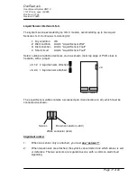
Liquid Sensor Option

System KMP-V accepts one or two liquid sensors type LS-X after installation of interface
ILS-C. The LS-X liquid sensor responds to a water aggregation touching both its
electrodes, and can hence cause the control box to issue an alarm and if desired close
the cut-off valve when wet.
Liquid sensors are laid out where there is particular risk of water aggregation, e.g. under
a buffer tank, or by a floor drain.
Jumper row F5 determines if the valve should close when the sensor gets wet.

A liquid sensor alarm remains active while the sensor is wet, and is automatically
acknowledged once the sensor gets dry. To clear a liquid sensor alarm, it is therefore
necessary to remove the aggregated water and wipe the sensor dry.

The liquid sensor is continuously monitored, and erros such as a shorted or broken cable
are reported as system errors on the front panel as described in an earlier section.

Liquid Sensor Setting: Jumper Row F

Pos 4:   Liquid Sensor and Interface Attachment.

  Jumper absent   = No liquid sensor installed / liquid sensor deactivated
  Jumper present  = Liquid sensor and interface installed and active

Pos 5:   Liquid Sensor Valve Control

  Jumper absent   = Alarm only
  Jumper present  = Valve closes on wet liquid sensor

Functional test of liquid sensor

Liquid sensors are tested thus:

1.  Inspect jumper setting to establish liquid sensor configuration (see above)

2.  Place a wet rag over the liquid sensor so that it touches both its electrodes.

3.  After a 10 second delay, the KMP-V should issue a wet sensor alarm, and if

configured to close the cut-off valve should do so as well.

Now remove the rag and wipe the liquid sensor dry; the system must revert to the Normal
state.

Содержание System KMP-V

Страница 1: ...DanTaet System KMP V User Manual H jmevej 36 38 DK 5250 Odense SV Pho 45 63 17 45 00 Fax 45 63 17 45 01 Program 110101 func spec 160926...

Страница 2: ...kage Alarm Condition 10 System Error Condition 11 Liquid Sensor wet 12 Liquid Sensor defective 13 External Control 14 DIP1 ABA 14 DIP2 AIA 14 Digital Outputs 15 Liquid Sensor Option 16 Functional test...

Страница 3: ...readings from the water meter The KMP V front panel features six indicators and four control buttons Overview The Status indicator signals the actual system condition thus Steady Green System operati...

Страница 4: ...ion sensors in PIR mode Seepage Alarm During a 24 hour period the system seeks a lull in consumption of a preset duration during which consumption does not exceed a selected small value If such a lull...

Страница 5: ...t duration Key Holiday Pressing this button commences or terminates Holiday mode in which no meter indication is expected and the discharge limit is reduced to 20 litres typically This key is inoperat...

Страница 6: ...ilable or unsuitable Automatic Phase Switching PIR Automatic Phase Switching is achieved by having a signal from an attached motion sensor force the system into Presence High Phase for a preset time I...

Страница 7: ...e disturbance will be reported anew during the valve test Leakage Alarm Condition In Leakage Alarm Condition the water supply is cut off indicated by an extinguished Status indicator red light in the...

Страница 8: ...ence Valve tightness test in progress The water supply is temporarily cut off Consumption phase Low Holiday Absence Status Data Valve Max Alarm Seepage Alarm Consumption Status Data Valve Max Alarm Se...

Страница 9: ...Consumption The system is running in and cannot issue leakage alarms Key consumption values are measured and stored Consumption phase Low Holiday Absence Run In Status Data Valve Max Alarm Seepage Ala...

Страница 10: ...discharge The water supply has been cut off Max Alarm discharge after buzzer mute The water supply has been cut off Status Data Valve Max Alarm Seepage Alarm Consumption Status Data Valve Max Alarm S...

Страница 11: ...mmediate need of servicing Status Data Valve Max Alarm Seepage Alarm Consumption Communication error The water supply is unimpeded Communication error after buzzer mute The water supply is unimpeded S...

Страница 12: ...F5 inserted Liquid sensor wet alarm after buzzer mute The water supply is cut off Jumper F5 inserted Status Data Valve Max Alarm Seepage Alarm Consumption Status Data Valve Max Alarm Seepage Alarm Co...

Страница 13: ...or defective Status Data Valve Max Alarm Seepage Alarm Consumption Alarm attached liquid sensor is defective The water supply is unimpeded Jumper F5 not inserted Liquid sensor defective alarm after bu...

Страница 14: ...e a normally closed loop that is interrupted by a fire alarm or by the opening of a cabinet door This requires a change of digital input polarity by cfg3 ii1 DIP2 AIA Input 2 DIP2 J10 is used to steer...

Страница 15: ...mmon reference potential GND in connector J6 Terminal J6 1 supplies a synthesized meter impulse from the water meter The impulse value is selected in jumper row F positions 6 8 Terminal J6 2 is active...

Страница 16: ...emove the aggregated water and wipe the sensor dry The liquid sensor is continuously monitored and erros such as a shorted or broken cable are reported as system errors on the front panel as described...

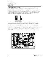
Страница 17: ...Fault Select number of attached sensors on J4 as shown near top edge of PCB close to heatsink with a jumper J4 1 2 2 liquid sensors attached J4 J4 2 3 1 liquid sensor attached sensor 1 sensor 2 The L...

Страница 18: ...s to normal operation Example Green indicators and nine short beeps nine hours Red indicators and 15 short beeps 15 minutes The clock s time is 9 15 Setting the Clock 1 Depress the Reset key for appro...

Страница 19: ...ur of suppression duration 4 The system reverts to normal operation Example Green indicators and 3 short beeps three hours Discharge monitor is suppressed for three hours by activation of Unlimited Se...

Страница 20: ...installed as per manufacturer s instructions Cut off Valve Electrically actuated ball or butterfly valve 24Vac supplied from KMP V The valve can be installed with any orientation with the actuator po...

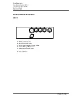
Страница 21: ...nc spec 160926 Doc No 417106 Revision 170823 Page 21 of 26 Socket and Gland Identification KMP V A 230Vac from mains B 24Vac to MULTICAL C LS X Liquid Sensor Alarm Relay D Alarm Relay PIR sensor E Dat...

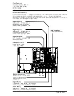
Страница 22: ...a 24Vac power supply module Mains Connection 230Vac PE N L via key switch Alarm Relay Terminal J17 Max 24Vac NC COM NO Volt free relay excited in the Normal condition Signal Relay Terminal J16 Max 24V...

Страница 23: ...onnect two metal pins on the circuit board when inserted over these A pair of small tweezers or needle nose pliers may be helpful for the relocation of jumpers CAUTION Disconnect the mains supply befo...

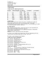
Страница 24: ...value 20 l h is used adjustable by PC hpcof and automatically after a minimum 7 day run in L No jumper in row B Discharge monitor disabled in both phases Otherwise the jumper setting is used in Phase...

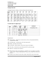
Страница 25: ...VEN 2 out in out INH VFO HDY VCL 3 out in in INH VFO HDY 4 in out out INH HIP 5 in out in INH VFO HIP 6 in in out INH HIP VFO 7 in in in INH VFO HIP VFO Abbreviations INH Inhibit suppress activation r...

Страница 26: ...DanTaet a s User Manual System KMP V 110101 func spec 160926 Doc No 417106 Revision 170823 Page 26 of 26 EU Declaration of Conformity...

Отзывы: