


4 Electrical Installation
4.1 Control Wiring
4.1.1 Ways to Control the Soft Starter
Control the soft starter in 3 ways:
•
Pressing the keys on the LCP.
•
Via remote inputs.
•
Via a serial communication link.
The VLT
®
Soft Starter MCD 500 always responds to a local
start or stop command (via the [Hand On] and [Off] keys
on the LCP). Pressing the [Auto On] key selects remote
control (the soft starter accepts commands from the
remote inputs). In remote mode, the Auto On LED is on. In
hand-on mode, the Hand On LED is on if the soft starter
starts or runs. The Off LED is on if the soft starter is
stopped or stops.
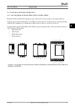
4.1.2 Control Terminals
Control terminations use 2.5 mm
2
(14 AWG) plug-in
terminal blocks. Different models require control voltage to
different terminals:
•
CV1 (24 V AC/V DC): A5, A6.
•
CV2 (110–120 V AC): A5, A6.
•
CV2 (220–240 V AC): A4, A6.
Illustration 4.1 Wiring to Control Terminals
NOTICE
Do not short terminals 05 and 06 without using a
thermistor.
All control terminals and relay terminals comply with SELV
(safety extra low voltage). This protection does not apply
to grounded delta leg above 400 V.
To maintain SELV, all connections made to the control
terminals must be PELV (for example thermistor must be
reinforced/double insulated from motor).
NOTICE
SELV offers protection by way of extra low voltage.
Protection against electric shock is ensured when the
electrical supply itself is of the SELV type and the instal-
lation follows local/national regulations on SELV supplies.
NOTICE
Galvanic (ensured) isolation is obtained by fulfilling
requirements for higher isolation and by providing the
relevant creepages/clearance distances. These
requirements are described in the IEC 61140 standard.
The components that make up the electrical isolation
also comply with the requirements for higher isolation
and the relevant test as described in IEC 61140.
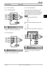
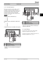
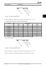
4.1.3 Remote Inputs
The soft starter has 3 fixed inputs for remote control.
Control these inputs by contacts rated for low voltage, low
current operation (gold flash or similar).
1
7
7
H
A
5
0
4
.1
0
Start/stop
Reset
Start
Stop
Reset
Start
Stop
Reset
15
16
17
18
25
18
15
16
17
18
25
18
15
16
17
18
25
18
2
3
1
1
2-wire control
2
3-wire control
3
4-wire control
Illustration 4.2 2-, 3-, and 4-wire Control
The reset input can be normally open or normally closed.
To select the configuration, use
parameter 3-8 Remote Reset
Logic
.
WARNING
ELECTRICAL SHOCK HAZARD
Do not apply voltage to the control input terminals.
These terminals are active 24 V DC inputs and must be
controlled with potential-free contacts.
•
Segregate cables to the control inputs from
mains voltage and motor cabling.
Electrical Installation
Operating Guide
MG17K602
Danfoss A/S © 05/2016 All rights reserved.
13
4
4


