


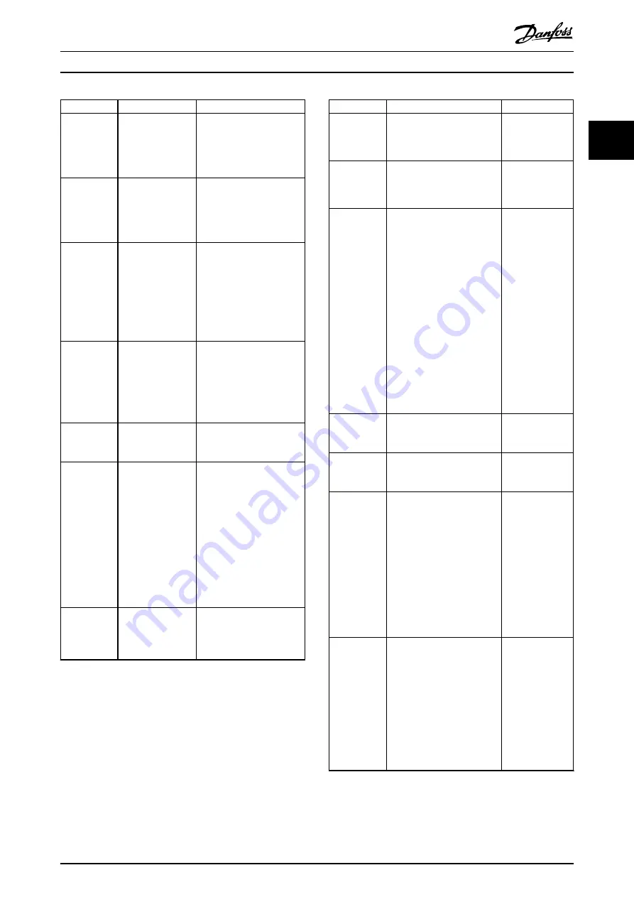
Function
Description
Limits/errors
AUX
overvoltage
When the AUX
voltage rises above
a certain level, a
warning/error is
issued.
•
Warning: >53 V
•
Error: >56 V
AUX
undervoltage
When the AUX
voltage drops
below a certain
level, a warning/
error is issued.
•
Warning: <21.6 V
•
Error: <19 V
AUX
overcurrent
When the AUX
current rises above
a certain level, a
warning/error is
issued.
•
Warning: >90% of user-
defined limit
•
Error: >100% of user-
defined limit
The default value of
15 A is used if no limits
are defined by the user.
Brake error
The SAB reports
various brake-
related errors.
•
Shorted brake resistor
•
Shorted brake IGBT
•
Thermal overload
•
Disconnected brake
resistor
Inrush fault
The SAB can handle
up to 2 inrush
cycles per minute.
Error issued if >2 inrush
cycles occur per minute.
Mains phase
loss
The SAB detects
the mains phase
loss and issues a
warning/error when
limits are reached.
•
Warning: 3–10% mains
phase imbalance
•
Error:
-
>10% mains
phase
imbalance
-
3–10% mains
phase
imbalance for
>10 minutes
STO 1 & STO
2 indicators
The SAB indicates
the presence of the
STO 1 & STO 2
voltage.
LED on: STO deactivated
LED off: STO activated
Table 2.10 Additional Protection Features for SAB
2.10.5.2 VLT
®
Integrated Servo Drive
ISD 510
The VLT
®
Integrated Servo Drive ISD 510 has the additional
protection features detailed in
.
Function
Description
Limits/errors
UDC
overvoltage
When the DC-link voltage
rises above a certain level, a
warning/error is issued.
•
Warning:
>810 V
•
Error: >820 V
UDC
undervoltage
When the DC-link voltage
drops below a certain level, a
warning/error is issued.
•
Warning:
<410 V
•
Error: <373 V
Overcurrent at
output
To protect the servo drive
and any machinery attached
to the servo drive shaft, a
current limit protection is
implemented. The current
limit protection on the servo
drive is available for motor
phase current. All 3 phase
currents are constantly
monitored. If an overcurrent
occurs, the servo drive stops
the actual operation. The
servo drive stops the shaft
rotation, engages the brake
(if present), and an error is
issued.
•
Size 1: >8 A
•
Size 2: >9 A
Motor
position
CRC check of each encoder
value, resolver amplitude, and
consistency check.
–
Brake control The brake current is
controlled by the servo drive
firmware.
–
Maximum
shaft speed
The shaft speed of each
servo drive type is limited to
protect the motor mechanical
parts.
Maximum motor
speed:
•
Size 1, 1.5 Nm:
7000 RPM
•
Size 2, 2.1 Nm:
6000 RPM
•
Size 2, 2.9 Nm:
5000 RPM
•
Size 2, 3.8 Nm:
4000 RPM
Torque limit
The application peak torque
limit [M
max
] can be set via
parameters
52-15
,
52-23
, and
52-36 Application Torque Limit
(0x2053)
.
The maximum torque per
servo drive is calculated as:
Maximum phase current x
torque factor
Peak torque M
max
:
•
Size 1, 1.5 Nm:
6.1 Nm
•
Size 2, 2.1 Nm:
7.8 Nm
•
Size 2, 2.9 Nm:
10.7 Nm
•
Size 2, 3.8 Nm:
12.7 Nm
Table 2.11 Additional Protection Features for ISD 510
Servo Drive
System Overview
Design Guide
MG36C102
Danfoss A/S © 08/2017 All rights reserved.
25
2
2


