130B
T334.10
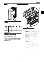
Illustration 2.14 Control Wiring Access for A4, A5, B1, B2, C1 and
C2 Enclosures
See
before tightening the covers.
Frame
IP20
IP21
IP55
IP66
A4/A5
-
-
2
2
B1
-
*
2.2
2.2
B2
-
*
2.2
2.2
C1
-
*
2.2
2.2
C2
-
*
2.2
2.2
* No screws to tighten
- Does not exist
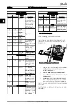
Table 2.3 Tightening Torques for Covers (Nm)
2.4.5.2 Control Terminal Types
shows the removable frequency converter
connectors. Terminal functions and default settings are
summarized in
1
4
2
3
130BA012.11
61
68
69
39
42
50
53
54
55
12
13
18
19
27
29
32
33
20
37
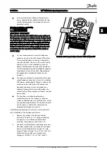
Illustration 2.15 Control Terminal Locations
•
Connector 1 provides four programmable digital
inputs terminals, two additional digital terminals
programmable as either input or output, a 24 V
DC terminal supply voltage, and a common for
optional customer supplied 24 V DC voltage
•
Connector 2 terminals (+)68 and (-)69 are for an
RS-485 serial communications connection
•
Connector 3 provides two analog inputs, one
analog output, 10 V DC supply voltage, and
commons for the inputs and output
•
Connector 4 is a USB port available for use with
the MCT 10 Set-up Software
•
Also provided are two Form C relay outputs that
are in various locations depending upon the
frequency converter configuration and size
•
Some options available for ordering with the unit
may provide additional terminals. See the manual
provided with the equipment option.
See
for terminal ratings details.
Installation
VLT
®
HVAC Drive Operating Instructions
MG11AH02 - VLT
®
is a registered Danfoss trademark
17
2
2


