


4.29 Magnetic Bearings
4.29.1 Magnetic Bearings Function
The compressor shaft and impellers levitate during operation and float on a magnetic cushion created by the
magnetic bearings. Permanent magnets do most of the work and electromagnets are used for trimming the shaft
position within 0.0003” (7 microns). One axial (Z axis) and two radial (X & Y axis) magnetic bearings are used to
maintain shaft position. Centered rotation is instantaneously self-corrected and maintained by the bearing control
loop. Refer to Figure 4-252 Bearing Control Signal Flow on page 226.
When not powered, the shaft is supported by carbon composite or roller touchdown bearings.
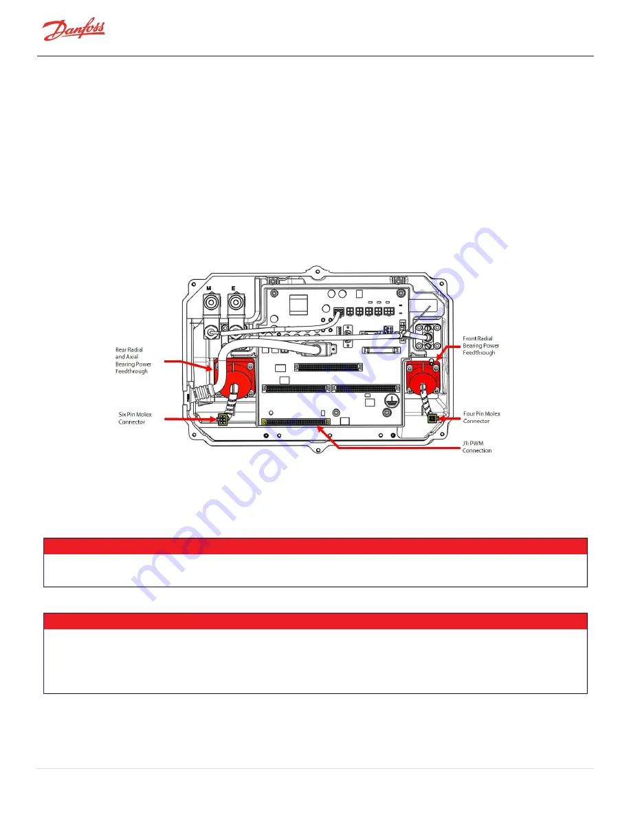
4.29.2 Magnetic Bearings Connections
PWM connectors supply power at the bearing power feedthroughs. Refer to Figure 4-255 Bearing Connections.
Figure 4-255 Bearing Connections
4.29.3 Bearing Verification
4.29.3.1 Bearing Coil Verification
• • • CAUTION • • •
Do not attempt to perform an insulation (megger) test on a component under vacuum. This can cause insulation breakdown or failure
during the testing process.
NOTE
l
To check bearing coil insulation integrity, a Mega ohm meter (e.g., Megger) set to 1KV should be used. Readings from coils
to ground should be greater than 100MΩ, and readings between coils should be greater than 100MΩ.
l
A faulty PWM Amplifier may be the result of a bearing failure and may cause a failure of the Potted DC-DC Converter
resulting in a blown F1 fuse on the Closed Top Soft Start. If a bearing coil is found to be faulty, then the PWM, Potted DC-DC
Converter, and Closed Top Soft Start F1 fuse must be verified as well.
Page 230 of 294 - M-SV-001-EN Rev. H 1/23/2023
Содержание Turbocor TT Series
Страница 2: ...THIS PAGE INTENTIONALLY LEFT BLANK Page 2 of 294 M SV 001 EN Rev H 1 23 2023...
Страница 14: ...Page 14 of 294 M SV 001 EN Rev H 1 23 2023 THIS PAGE INTENTIONALLY LEFT BLANK...
Страница 16: ...Page 16 of 294 M SV 001 EN Rev H 1 23 2023 THIS PAGE INTENTIONALLY LEFT BLANK...
Страница 18: ...Figure 1 2 New Type Code Page 18 of 294 M SV 001 EN Rev H 1 23 2023...
Страница 39: ...Figure 2 6 Compressor Energy and Signal Flow Connections M SV 001 EN Rev H 1 23 2023 Page 39 of 294...
Страница 46: ...Page 46 of 294 M SV 001 EN Rev H 1 23 2023 THIS PAGE INTENTIONALLY LEFT BLANK...
Страница 250: ...Page 250 of 294 M SV 001 EN Rev H 1 23 2023 THIS PAGE INTENTIONALLY LEFT BLANK...
Страница 268: ...Figure 5 3 Bearing Calibration Flow Page 268 of 294 M SV 001 EN Rev H 1 23 2023...
Страница 274: ...Page 274 of 294 M SV 001 EN Rev H 1 23 2023 THIS PAGE INTENTIONALLY LEFT BLANK...
Страница 282: ...Figure B 2 Compressor Operation Troubleshooting Flowchart Sheet 2 Page 282 of 294 M SV 001 EN Rev H 1 23 2023...
Страница 283: ...Figure B 3 Compressor Voltage Troubleshooting Flowchart Sheet 1 M SV 001 EN Rev H 1 23 2023 Page 283 of 294...
Страница 284: ...Figure B 4 Compressor Voltage Troubleshooting Flowchart Sheet 2 Page 284 of 294 M SV 001 EN Rev H 1 23 2023...
Страница 285: ...Figure B 5 Compressor Voltage Troubleshooting Flowchart Sheet 3 M SV 001 EN Rev H 1 23 2023 Page 285 of 294...
Страница 286: ...Page 286 of 294 M SV 001 EN Rev H 1 23 2023 THIS PAGE INTENTIONALLY LEFT BLANK...
Страница 290: ...Page 290 of 294 M SV 001 EN Rev H 1 23 2023 THIS PAGE INTENTIONALLY LEFT BLANK...
Страница 292: ...Page 292 of 294 M SV 001 EN Rev H 1 23 2023 THIS PAGE INTENTIONALLY LEFT BLANK...


