5
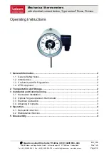
Models with remote sensor inputs
Terminal block for remote control/sensing
is located on the circuit board above the
battery compartment.
RX1
RX2 & RX3
1 2 3 4
ELECTRONICS
N L
COM
ZONE
1 ON
ZONE
1 OFF
A
ELECTRONICS
B C 1 2 3 4 5 6
N
L
ZONE
1 ON
ZONE
1 OFF
ZONE
2 ON
ZONE
3 ON
COM
TERMINAL 6
RX3 ONLY
RX Receiver Wiring (RF models only)
1) For mains voltage operated systems link terminal 2 to mains live supply.
2) Power supply to unit must not be switched by timeswitch.
S1/D
S2/E
S1/D
S2/E
Window or
teleswitch
contact
(NO or NC)
Teleswitch
contact (NC)
Window
contact (NC)
S1/D
S2/E
Confi gured for
remote room
sensor or limit
sensor
Confi gured for
window contact or
other contact such
as teleswitch
Confi gured for
window contact
and other contact
such as teleswitch
/D
/E
Remote
control
connections
2) limit sensor, for example, fl oor temperature sensor (sold as
accessory).
3) window contacts, card reader contacts or teleswitch contacts.
See
Installer Advanced Programming Options
for set-up instructions.
Installa
tion Instruc
tions
GB
Содержание TP5001 series
Страница 40: ...40 RF TP5001 TP5001 RF TP5001M 2 5 75 C 2 1 C 1 15 15 30 100 UA...
Страница 41: ...41 TP5001 1 2 3 L N D E S1 S2 A M 230 1 5 2 DIL 1 2 UA...
Страница 42: ...42 TP5001 TP5001 TP5001 TP5001A TP5001MA 1 2 3 TP5001 TP5001 RF RESET D E UA...
Страница 44: ...44 RF RX1 RX 1 5 1 TP5001 RF reset 2 V 3 TP5001 RF 3 3 RX1 PROG CH1 3 4 RX2 1 1 3 5 2 1 2 PROG CH2 RX2 RESET UA...
Страница 45: ...45 RX3 1 1 3 5 2 1 2 PROG CH2 RX2 5 3 1 2 PROG CH3 RX3 5 TP5001 RF V TP5001 TP5001 UA...
Страница 46: ...46 a V PROG 3 b V PROG 5 c V d RUN PROG UA...
Страница 47: ...47 30 30 V 40 5 C 30 C 31 31 V 5 40 C 5 C 32 32 V 0 1 33 33 V 0 1 UA...
Страница 48: ...48 34 34 V 0 3 3 6 6 9 9 12 12 35 34 3 6 9 12 PI 35 V 2 5 2 5 5 5 10 10 36 36 V 0 1 2 C 2 UA...
Страница 49: ...49 38 38 V 0 1 37 36 1 2 37 V 0 1 1 2 2 3 3 4 4 40 2 4 6 40 V 1 2 4 6 UA...
Страница 50: ...50 70 DIL 1 70 V 0 1 71 24 230 2 90 71 V 0 1 41 5 2 24 5 2 24 41 V 5 2 5 2 24 24 UA...
Страница 51: ...51 81 1 5 K 81 V 1 5 0 C 74 74 V 0 1 73 73 V 000 999 000 72 72 V 00 99 Factory setting is 00 UA...
Страница 52: ...52 90 A 90 V 0 1 2 93 3 94 93 A 90 2 93 V 2 C F10 20 50 C 27 C UA...
Страница 53: ...53 94 A 90 3 94 V 0 1 UA...