User Guide | Optyma™ iCO2
38 | BC408445719305en-000101
© Danfoss | Climate Solutions | 2023.01 | LCA012A030
(3) Method to purge CO2 refrigerant
(a) Turn the power ON at the state that SW5-7 on the PCB of the refrigeration unit is switched ON. With this procedure, operation is prohibited and EEVG,
EEVSC and EEVLB1, 2 become fully opened.
(b) Turn the power OFF for safety.
(c) Remove the cap of service valve and connect gauge manifold. (It will be sufficient if you turn the nut by 1/8 turn.)
(d) Open the service valve little by little and purge the CO2 refrigerant.
(Note) If purging CO2 refrigerant instantly, a lot of refrigerant oil may be purged together with the CO2 refrigerant like dry ice. Accordingly be sure to
purge it little by little. And then, since CO2 is 1.5 times as heavy as the air, do not purge it at a place such as manhole where CO2 may stay.
(e) After purging almost of all amount of refrigerant charged in the refrigeration unit, attach a gauge manifold and purge the residual refrigerant merged
into the refrigerant oil by using evacuation pump.
(f ) After completion of purging work, switch OFF the SW5-7 on the PCB of the refrigeration unit.
(4) Relocation, disposal and servicing
• When the Condensing unit is relocated and reinstalled after moving to new address, or other, specialized techniques are required. Consult your dealer
or specified contact desk of maker.
• When disposing the Condensing unit, although it is not necessary to collect the refrigerant, consult your dealer or specified contact desk of maker.
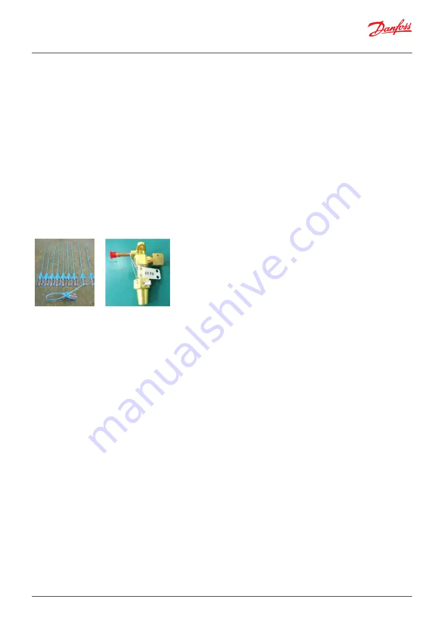
(5) When safety valve closed/seal broken during servicing (before Pressure Relief Valve)
• In the event of servicing / Replacement of pressure Relief Valve, the service personnel must break the Factory installed seal / tag to close the Shut off
valve.
• When the shut off valve Seal/Tag opened after serving, service personnel must not apply the factory assembled seal/tag.
• Before completion of servicing the shut off valve must be included with fresh /new alternate seal/ tag to ensure the valve open position.
5.4 Warranty conditions of Condensing unit
(1) Scope not warranted
1. Nonconformity in the selection of model or design of Condensing unit.
When we judge that the failure has resulted from a fact that the installation work is made without observing instructions or cautions given in the
instruction manual, or the Condensing unit that has an excessively larger or smaller capacity is selected for the cooling load.
(Example: Mistake in selection of expansion valve, improper installation, omission of solenoid valve in liquid line, etc.)
2. Nonconformity in the selection of low pressure device.
• When the low pressure device doesn’t satisfy the requirements described in Instruction manual, Page 9.
3. When any items other than the followings specified by us are used.
• Refrigerant R744
• Condensing unit oil “Diamond Freeze MA68”
4. Nonconformity in installation work
• Damage caused by improper handling during installation work
• When it is judged that foreign matters entered in the cycle during installation piping work.
• When it is judged that electric wires have been connected improperly during installation.
• When matters have not been improved although our supervisor warned improper practice during installation.
• Accident resulted from violating relevant laws or regulations.
• When it has been operated neglecting larger vibration or operating noise.
• When the failure was caused by weak foundation or fragile support frame.
5. Accident resulted from modification, incidental work or relocation at site, or overriding protective devices provided on our product.
6. Accident resulted from installing on vehicle, rail car, ship, or other mobile carrier.
7. Accident resulting from nonconformity in operating environment, maintenance and inspection.
• Accidents resulting from installation in the environment impregnated with corrosive gas such as oil (including machine oil), salt (coast area) and
sulfide gas.
• Accident related to installation place (shortage of air blow volume, special environmental conditions like hydraulic pressure, chemicals, etc.)
• Accident caused by maladjustment (overheat degree of expansion valve, pressure switch setting at low pressure side).
• Accident by short-cycle operation (operation and stop of less than 3 minutes each).
• Improper maintenance (clogged gas cooler fins, overlooked inspection and cleaning of fouling, inspection and replacement of dirty Condensing unit
oil and gas leak).
• Mistake in repair work (use of wrong parts, missing parts, improper installation).
• Accident caused by overcharge or shortage of refrigerant or Condensing unit oil (start failure, poor cooling of motor, improper lubrication).
• Accident owing to insufficient defrost operation.
Note:
The Shut off valve position must be fully opened condition before and during operation.
The factory assembled seal / identification cannot be reused after the servicing.
Shut off Valve hole diameter is 2mm.
Alternate seal or tag
Factory assembly


