System design recommendations
Expansion device
When the parallel installation is serving a single
evaporator system, the dimensioning of the
expansion device (thermostatic or electronic)
becomes critical and must be made in relation
to both minimum and maximum capacity.
This will ensure correct superheat control in all
situations, with a minimum of 5 K superheat at
the compressor suction. The expansion device
should be sized to ensure proper control of
the refrigerant flow into the evaporator. An
oversized valve may result in erratic control.
Proper selection could imply a slightly undersized
expansion valve at full load. This consideration
is especially important in manifolded units
where low load conditions may require the
frequent cycling of compressors. This can lead
to liquid refrigerant entering the compressor
if the expansion valve does not provide stable
refrigerant superheat control under varying
loads. The superheat setting of the expansion
device should be sufficient to ensure proper
superheat levels during low loading periods. A
minimum of 5 K stable superheat is required.
In addition, the refrigerant charge should be
sufficient to ensure proper subcooling within the
condenser so as to avoid the risk of flashing in the
liquid line before the expansion device.
The refrigeration compressor is designed to
compress vapor only. A suction line accumulator
prevents compressor damage from a sudden
surge of liquid refrigerant and oil that could enter
the compressor from the suction line. For low
temperature application, suction accumulator
is a must unless approved by careful tests under
different operating conditions. If the system use
hot gas bypass or reversible defrost method,
suction accumulator is necessary.
Selection of a suction line accumulator should
be made on the basis of the following three
capabilities:
1. The accumulator should have an adequate
liquid-holding capacity that can vary with the
system. Normally this should not be less than
50% of the system charge. If possible, this value
should be checked based on actual tests.
2. The accumulator should perform without
adding excessive pressure drop to the system.
3. An accumulator should have the capability of
returning oil at the proper rate and under a range
of load conditions.
Guideline of suction accumulator needs to be
respected in making a selection.
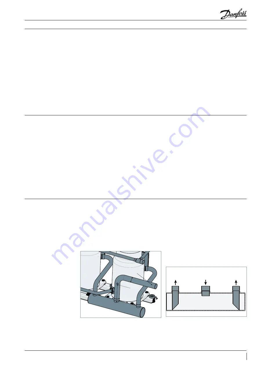
For efficient oil management in parallel systems
the oil should return to the compressor at
approximately the same rate as it leaves so
that an appropriate oil level can always be
maintained.
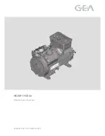
Danfoss recommends an adequately sized
suction header which provides equal distribution
of returning refrigerant and oil to each individual
compressor. The suction lines from the header
towards each individual compressor must be
fitted into the suction header. This configuration
will result in a higher gas velocity at the pick-up
tube inlet and proper oil return when the oil
level in the suction header rises. The compressor
suction lines must always enter the suction
header on the topside. A recommended suction
header design is shown below.
Suction accumulator
Suction header
Main suction line
Oil injection port
H
D
Suction gas
Suction gas to
compressor
47
FRCC.PC.035.A4.02
Application Guidelines
Manifold compressors
Содержание MLM116
Страница 1: ...Danfoss Scroll for Refrigeration MLM MLZ116 50Hz R404A R22 Application guidelines http cc danfoss com ...
Страница 2: ......
Страница 3: ...Content Single compressors 4 Manifold compressors 39 3 FRCC PC 035 A5 02 Application Guidelines ...
Страница 58: ......
Страница 59: ......


