Assembly
2.1 Suspension options
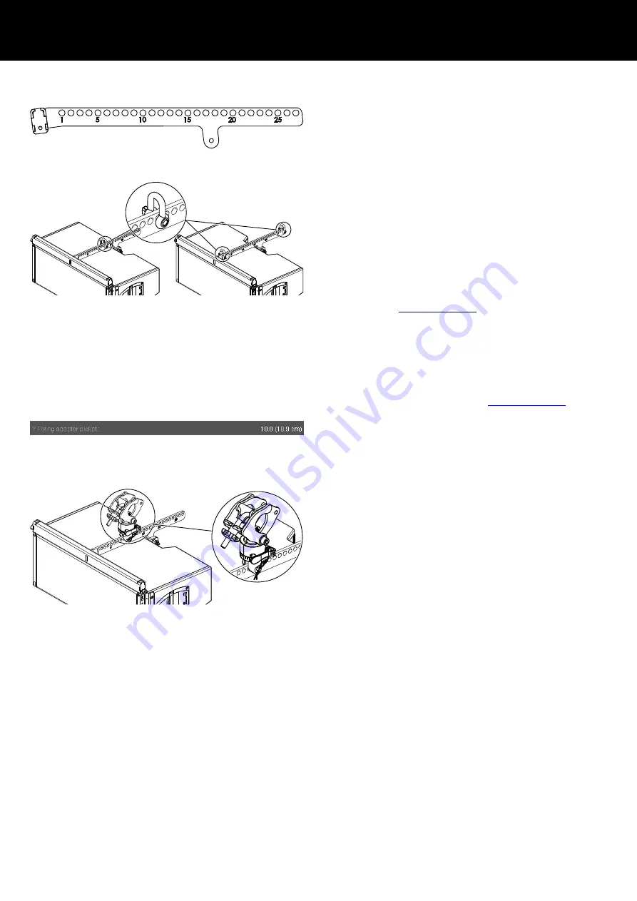
The center bar of the adapter is equipped with a total of 27 holes
to allow the suspension of the array and the setting of different
vertical angles.
The holes are numbered with an increment of five.
Single or dual pick point operation
The array can be suspended using one or two E6507 1t shackle(s)
and appropriate lifting devices or steel wire ropes.
With "Dual pick point operation", the vertical aiming of the entire
array is set by trimming the respective lifting devices.
With "Single pickpoint operation", the overall vertical aiming of the
entire array is defined by using a particular hole of the hole index
of the center bar.
The corresponding hole position is calculated using the d&b
ArrayCalc simulation software. For this purpose, ArrayCalc can be
downloaded at
www.dbaudio.com
.
Note: Please note that you have to check the «Rigging plot»
page within ArrayCalc, as the «Sources» page only indicates
hole numbers for the Z5390Y Flying frame, but not for the
Z5394 Y Flying adapter.
The use of ArrayCalc is described in "TI 385 d&b Line array
design, ArrayCalc" which is included in the ArrayCalc software.
The TI can also be downloaded at
www.dbaudio.com
.
In ArrayCalc, the closest pickpoint hole and the exact distance in
cm/inch are displayed in the «Main» array section
Þ
«Pickpoints and load» (last entry) on the «Rigging plot» page,
provided the corresponding array is selected on this page.
Z5147 Rota clamp option
Alternatively, the array can be suspended and horizontally aligned
from a single pickpoint using the d&b Z5147 Rota clamp. The
clamp allows the load to be attached to overhead bars or truss
with a tube diameter of up to 50 mm (2”).
Attachment
Choose the appropriate hole position in the center bar according
to the ArrayCalc calculation and attach the Rota clamp
correspondingly.
Note: Please observe the relevant mounting instructions which
are enclosed with the Rota clamp.
2.2 Preparing the setup
General
Check the acoustical and mechanical setup using ArrayCalc and
prepare enough printouts for each array.
The plan enables the riggers to set up the suspension points, the
securing points and the chain hoists.
When on site first:
▪ Clear the working areas and ensure there is enough space to
set up and lift the array.
▪ Check that the hoists are exactly in the specified position.
▪ Ensure the chains are not twisted.
▪ Prepare the cables and link cables according to the number of
amplifier channels and cabinets used.
2 Assembly
d&b Z5394 Rigging manual 1.2 en
5


