background image

116  

  Technical Specifications 

Genie HM-HC Series-GigE Vision Camera 

Comparison of a 2/3 Inch and 1 Inch Lens used with a Genie HM 1400 

Ø16.00

7.

60

10.40

12

.88

Genie HM 1400 Sensor

Ø11.00

1 inch Lens Coverage

2/3 inch Lens Coverage


Lens Sensor Size vs. Genie HM model 

Each Genie HM sensor has a square pixel of 7.4 x 7.4 µm. The following table lists the lens size required for total 
illumination and the next smaller lens size which will have some vignetting.  
 

Genie Model 

Illumination Coverage 

Genie HM 1400 

Genie HM 1024 

Genie HM 640 

Complete Illumination 

1 inch Lens 

2/3 inch Lens 

1/3 inch Lens 

Some Vignetting 

2/3 inch Lens 

1/1.8 Lens 

1/4 inch Lens 


Содержание Genie HC1024

Страница 1: ...Genie HM HC Series Camera User s Manual Genie Framework 1 80 HM640 HM1024 HM1400 HM1400 XDR HC640 HC1024 HC1400 GigE Vision Area Scan Camera CA GENM HUM00 www imaging com ...

Страница 2: ...eir respective owners Document Date October 13 2010 Document Number CA GENM HUM00 CA GENM HUM00 About DALSA DALSA is an international high performance semiconductor and electronics company that designs develops manufactures and markets digital imaging products and solutions in addition to providing wafer foundry services DALSA Digital Imaging offers the widest range of machine vision components in...

Страница 3: ...19 WARNING GROUNDING INSTRUCTIONS 19 GIGE NETWORK ADAPTER GUIDELINE 19 Supported Network Configurations 19 INSTALLATION OVERVIEW PREPARATIONS 20 Network and Computer Overview 20 Installation Overview 21 Preventing Operational Faults due to ESD 21 SAPERA LT LIBRARY INSTALLATION 22 GENIE CD PACKAGE INSTALLATION 23 Procedure 23 GigE Server Verification 23 CONNECT THE GENIE CAMERA 24 Connectors 24 Sta...

Страница 4: ...apera LT or GigE Vision Compliant Applications 52 CAMEXPERT I O CONTROLS DIALOG 53 GENERAL INPUTS 54 External Input Signal Opto coupler Debounce Circuit 54 General Inputs Settings Via CamExpert 54 Input Controls via Sapera LT or GigE Vision Compliant Applications 55 STROBE AND GENERAL OUTPUTS 56 General Outputs Settings via CamExpert 56 Open and Close Output Settings 57 Strobe On Start of Exposure...

Страница 5: ...re Interdependence Diagrams 85 Trigger Enable TRUE 86 Trigger Enable FALSE 86 Output Selector 87 Vertical Binning 87 Horizontal Binning 88 Pixel Format 88 Network Configuration Mode 89 Miscellaneous Dependencies 89 Accessing the Genie User Buffer 90 NETWORK OVERVIEW TOOLS 93 GENIE IP CONFIGURATION MODE DETAILS 93 Link Local Address LLA 93 DHCP Dynamic Host Configuration Protocol 94 Persistent IP 9...

Страница 6: ...ng a Filter 121 COMPUTER REQUIREMENTS FOR GENIE CAMERAS 122 Host PC System 122 Ethernet Switch Requirements 122 IEEE 802 3x Pause Frame Flow Control 122 Ethernet to Fiber Optic Interface Requirements 123 EC FCC DECLARATION OF CONFORMITY 124 TROUBLESHOOTING 125 OVERVIEW 125 Problem Type Summary 125 Verifying Network Parameters 127 Before Contacting Technical Support 127 INSTALLATION ISSUES AND FUNC...

Страница 7: ...Genie HM HC Series GigE Vision Camera Contents 5 GENIE TECHNICAL SUPPORT 132 GLOSSARY OF TERMS 133 INDEX 137 ...

Страница 8: ...6 Contents Genie HM HC Series GigE Vision Camera ...

Страница 9: ...cquisition while the HC camera series using the same sensor with a Bayer filter provides color acquisition All Genie cameras are supported by DALSA Sapera LT software libraries featuring CamExpert for simplified camera set up and configuration Sapera LT is field proven in thousands of robust industrial applications Hardware independent Sapera LT delivers the same reliable performance regardless of...

Страница 10: ...lutions Monochrome or color acquisition High frame rates relative to similar products Digital binning for increased sensitivity Lookup table pre processing Real time shading correction i e Flat Field processing Horizontal Flip function Supports several trigger modes for image capture control 2 opto isolated inputs 2 opto isolated outputs Native Trigger to Image Reliability design framework Visual ...

Страница 11: ...Product Number Genie Framework composed of the Sapera network Imaging Package Genie Imaging Driver and latest Genie Firmware Required installation Included with Genie distribution CD Sapera Runtime including CamExpert Included and installed if desired GenICam support XML camera description file Embedded within Genie Sapera LT version 6 10 or later Sapera 7 required for 64 bit support Provides ever...

Страница 12: ...e on the HC models Binning Digitally based Horizontal 2 pixel and Vertical 2 line All HM models Note Binning is not available on the HC models Timestamp 1µs internal timer or external signal to timestamp images and events Test image Internal generator with choice of static and shifting patterns User settings Select factory default or one user camera configuration Optical Interface Back Focal Dista...

Страница 13: ...5 m s2 Sweep rate 1 octave per minute Duration 1 sweep cycle to and fro Random vibrations MIL STD 810E 1989 method 514 4 Category 10 Levels and frequencies 0 04 g2 Hz from 20 to 1000 Hz 6 dB oct from 1000 to 2000 Hz Duration 1 hour Shocks IEC 68 2 27 1987 Test Ea and guide Shape half sine Amplitude 75 g Duration 3 ms Number 3 shocks and 3 shocks Supported Industry Standards Genie cameras are 100 c...

Страница 14: ... Frame Rate free running Dependent on Genie HM HC model see Partial Scan Window ROI Minimum Exposure 10μs when using reset exposure mode triggered 56μs when using synchronous exposure mode free running Maximum Exposure 1 frame rate 10μs Internal Trigger to Start of Exposure 100μs Horizontal Line Time HM640 HC640 6 7μs HM1024 HC1024 10 3μs HM1400 HC1400 8 bit 14μs HM1400 HC1499 10 bit 22 3μs Pixel ...

Страница 15: ...d Maximum Achievable SNR 48 3 47 6 db With FFC Factory calibrated Full Well Capacity 24 000 electron Responsivity 30 6 DN nJ cm2 600 nm 2 55 x Gain HM1024 HC1024 Typical Min Units Notes Output Dynamic Range 47 5 45 7 db With FFC Factory calibrated Maximum Achievable SNR 47 1 45 9 db With FFC Factory calibrated Full Well Capacity 24 000 electron Responsivity 30 6 DN nJ cm2 600 nm 2 55 x Gain HM640 ...

Страница 16: ...view Genie HM HC Series GigE Vision Camera Genie HM HC Series Responsivity Note DALSA recommends using a 700nm cutoff filter with the HC color series cameras since the blue and green color filters become transparent above 700nm ...

Страница 17: ...length nm Genie HM HC Series Sensor Cosmetic Specifications The following table lists the current cosmetic specifications for the DALSA sensor used in the Genie HM HC series Blemish Specifications Maximum Number of Defects Hot Dead pixel defects 2 Single pixel defects 100 for HM series 25 for each individual color R G1 G2 B for HC series Clusters defects 0 Column defects 0 Row defects 0 Note All o...

Страница 18: ...el whose signal at nominal light illumination at 50 of the linear range deviates by more than 30 from the mean Cluster defect A grouping of more than 8 pixel defects Column defect A column which has more than 8 consecutive pixel defects Row defect A horizontal grouping of more than 8 consecutive pixel defects Test conditions Digital gain 1X Nominal light illumination at 50 of saturation Temperatur...

Страница 19: ...es for image processing and analysis Sapera Processing offers highly optimized tools for image processing blob analysis search pattern recognition OCR and barcode decoding The following is a Sapera application functional block diagram The Genie Framework installation includes the Genie driver and the Sapera Network Imaging Package User s Sapera Application Sapera LT SDK Genie Driver GigE Server Sa...

Страница 20: ...eries GigE Vision Camera GigE Vision Compliant Environment The GigE Vision Compliant XML device description file is embedded within Genie firmware allowing GigE Vision Compliant applications to know Genie capabilities immediately after connection ...

Страница 21: ... a variety of Gigabit network adapters both built into the system motherboard and as third party PCI adapters Supported Network Configurations The Genie obtains an IP address using the Link Local Address LLA or DHCP by default A LLA IP address is obtained in about 6 seconds with Microsoft Vista 7 or in about 1 minute with Microsoft XP If required a persistent IP address can be assigned see Running...

Страница 22: ...manual Genie also can connect through a Gigabit Ethernet switch When using VLAN groups the Genie and controlling computer must be in the same group refer to the DALSA Network Imaging Package user s manual If Genie is to be used in a Sapera development environment Sapera LT needs to be installed either before or after the Genie software package If Genie will be used in a GigE Vision Compliant envir...

Страница 23: ...e 97 Set up the other components of the imaging system such as light sources camera mounts optics encoders trigger sources etc Test with CamExpert Preventing Operational Faults due to ESD Genie camera installations which do not protect against ESD electrostatic discharge may exhibit operational faults Problems such as random packet loss random camera resets and random loss of Ethernet connections ...

Страница 24: ... or later must be installed Else Sapera LT is not required to control the Genie camera Insert the DALSA Sapera CD ROM If AUTORUN is enabled on your computer the DALSA installation menu is presented If AUTORUN is not enabled use Windows Explorer and browse to the root directory of the CD ROM Execute launch exe to start the DALSA installation menu and install the required Sapera components The insta...

Страница 25: ...pera LT run time which includes CamExpert Follow the on screen prompts and reboot when the installation is complete GigE Server Verification After a successful Genie Framework package installation the GigE Server icon is visible in the desktop taskbar tray area After connecting a camera see following section allow a few seconds for the GigE Server status to update The Genie camera must be on the s...

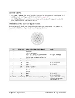
Страница 26: ...ration Mode Details on page 93 See the next section Connectors on page 24 for an overview of the Genie interfaces Connectors The Genie has only two connectors A single RJ45 Ethernet connector for control and video data transmitted to from the host computer Gigabit NIC See Ruggedized RJ45 Ethernet Cables on page 119 for secure cables A single 12 pin Hirose male connector for camera power plus trigg...

Страница 27: ...rnet cable disconnected no link Steady Blue IP address assigned no application connected to the camera Steady Green Application connected Slow Flashing Green Triggered acquisition in progress Fast Flashing Green Free running acquisition in progress Once the Genie has its RJ45 connected to a network the Status LED will turn to steady blue when the IP address is assigned Only at this time will it be...

Страница 28: ...ce the Genie is assigned an IP address its Status LED is steady blue the GigE server tray icon will not have a red X through it indicating that the Genie device was found It might take a few seconds for the GigE Server to refresh its state after the Genie has obtained an IP address Right click the GigE Server tray icon to open the following menu Click on Show Status to open a window listing all de...

Страница 29: ...om the default of 15 seconds Configure the Windows firewall exception list Configure the NIC and camera IP settings Assign a User Defined name to a connected camera Assign a Persistent IP address to a camera instead of the default DHCP LLA assigned address Easily Configure the NIC as a DHCP server for connected GigE Vision camera Important Any changes made with this tool will update the Genie flas...

Страница 30: ...the DALSA Device Manager program from the windows start menu Start Programs DALSA Genie Firmware Update The right hand column shows whether a firmware update is Required or Not Required If an update is required click on the Automatic button The Update Firmware manager dialog opens and the new firmware version is written to the Genie camera The manual button allows the user to select from multiple ...

Страница 31: ...eated during the Genie software installation CamExpert will search for installed Sapera devices In the Device list area on the left side the connected Genie camera is shown or will be listed in a few seconds after CamExpert completes the automatic device search device discovery Select the Genie camera device by clicking on the camera user defined name By default the Genie camera is identified by i...

Страница 32: ... using CamExpert multiple Genie cameras on the network are seen as different Genie_M640_x devices as an example Click on a Genie device user name to select it for control by CamExpert An imaging application uses any one of these attributes to identify a camera its IP address MAC address serial number or User Name Some important considerations are listed below Do not use the camera s IP address as ...

Страница 33: ...d in the windows folder One simple method is to execute the Framework installer from within a batch file The batch file will have one command line As an example using the executable file name for Framework version 1 40 the command line is Genie_1 40 00 0222 Release exe r Important The executable name is enclosed in quotation marks This is required because of the space characters in the Genie Frame...

Страница 34: ...32 Installing the Genie Camera Genie HM HC Series GigE Vision Camera ...

Страница 35: ...ice All these features with the exception of the DeviceUserId are read only Sapera LT or GigE Vision Compliant calls are used to retrieve this information and correctly identify the camera along with its characteristics Following is an overview of CamExpert displaying this information followed by tables with the feature name associated to Sapera LT and to GigE Vision Compliant development environm...

Страница 36: ...ng to open the Power up configuration dialog box which allows you to specify camera power up configuration For more information see Power up Configuration on page 34 Power up Configuration Saved User Settings The Power up configuration dialog allows you to specify the camera configuration to load when powering up the camera The Genie camera flash memory contains two possible configuration settings...

Страница 37: ...general input pins GPO settings Defines the operational mode of the general output pins LUT Lookup Table function On or Off plus the LUT data HM models only Flat Field Correction FFC function On or Off plus the offset gain data see warning below Note Maximum frame rates and exposure durations saved previously with Genie Framework 1 40 may be slightly reduced by Framework 1 50 to improve acquisitio...

Страница 38: ...se parameters are visible under Camera Information and Sensor tabs See Accessing Features with Sapera LT on page 76 hidden table separator XML features for Camera and Sensor Information DeviceVendorName Name of camera vendor DeviceModelName Name of the camera model DeviceVersion Displays the device version which includes the firmware release and build DeviceFirmwareVersion Displays the currently l...

Страница 39: ...E Vision Compliant development environments Sensor Parameters Controls Via CamExpert The Sensor Parameters tab groups the parameters related to the camera sensor configuration for acquisition The following figure displays the CamExpert Sensor tab for the HM camera series Read Only Parameters Parameter Description Device Scan Type Displays the device scan type This is always area scan for Genie Col...

Страница 40: ...ion RGB balance adjustments can be saved with the camera user settings else they are lost when the camera is powered off See Bayer CFA Decoder Setting on page 100 Binning Horizontal Enables or disables horizontal binning Possible values are Disabled or 2 pixels When set to 2 pixels the image buffer width parameter is automatically adjusted For more information see Binning on page 45 Note Binning i...

Страница 41: ...e gain adjustment would be used to then get the full dynamic range With the Genie HM in 8 bit mode the offset values would change by 1 for each data entry of 4 i e black level units 1 4 DN Important The Genie gain adjustment range and 0dB point is arbitrarily defined by DALSA for the Genie camera series The reference setting of 0dB must not be compared to any other product s gain settings when eva...

Страница 42: ... Offset Scan Line Count Partial Image Scan Partial Scan Illustration Maximum Frame Rate fps Examples model HM1400 HM1400XDR HC1400 Free Running Acquisition synchronous mode Triggered Acquisition reset mode minimum 10μs exposure Vertical Lines Acquired Flat Field On Flat Field Off Flat Field On Flat Field Off 8 bit 10 bit 8 bit 10 bit 8 bit 10 bit 8 bit 10 bit 1024 64 32 75 37 64 32 75 37 768 86 43...

Страница 43: ...8 368 245 285 245 285 256 352 410 352 410 128 705 820 659 820 64 1317 1639 1160 1422 32 2320 2873 1872 2217 16 3745 4524 2702 3086 8 4587 4672 3472 3831 Maximum Frame Rate fps Examples model HM640 HC640 8 bit only Vertical Lines Acquired Free Running Acquisition synchronous mode Triggered Acquisition reset mode minimum 10μs exposure Flat Field On Flat Field Off Flat Field On Flat Field Off 480 301...

Страница 44: ...es not increase the maximum frame rate due to the CMOS sensor architecture Horizontal Crop Horizontal Scan offset Active Horizontal Scan Window ROI Vertical and Horizontal Cropping can be combined to grab only a region of interest ROI Besides eliminating post acquisition image cropping done by software in the host computer a windowed ROI grab reduces the bandwidth required on the Gigabit Ethernet ...

Страница 45: ...els Bayer Raw10 HC1400 only See Accessing Features with Sapera LT on page 76 XML features for Partial Scan and Window ROI Width Width of image region of interest must be an even value Height Height of image region of interest OffsetX Left coordinate of region of interest must be an even value in increments of 4 OffsetY Top coordinate of region of interest must be an even value in increments of 2 L...

Страница 46: ...plays the image buffer height Y axis in pixels OffsetX in Pixels Specifies the offset in X from the left of the image when using an ROI The image buffer width is automatically adjusted to compensate for this offset OffsetY in Lines Specifies the offset in Y from the top of the image when using an ROI The image buffer height is automatically adjusted to compensate for this offset Image Flip Enables...

Страница 47: ...tly by a factor of 2 in each axis Specifically if horizontal binning only is activated a nominal 640x480 image is reduced to 320x480 If vertical binning only is activated the image is reduced to 640x240 With both binning modes activated the resulting image is 320x240 With the Genie HM binning is performed digitally therefore there is no increase in acquisition frame rate The following graphic illu...

Страница 48: ...running trigger disabled The Genie free running mode has a programmable internal timer for frame rate and a programmable exposure period Frame rate is 0 1 fps to the maximum supported by the sensor Exposures range from 56µs to a maximum also dependent on the current frame rate This always uses Synchronous mode where exposure is aligned to the sensor horizontal line timing External trigger Exposure...

Страница 49: ...n page 49 trigger pulse width Following are details for each mode Note Do not change the exposure time while grabbing else an Invalid Trigger Event may be generated This applies to any exposure mode or trigger source The Invalid Trigger Event is not catastrophic and only indicates the loss of a video frame Stopping acquisitions first will avoid this error Free running Programmable Exposure Genie i...

Страница 50: ...1 timing for fastest possible frame rates Start of exposure is aligned on the next horizontal line while exposure duration granularity is 1µs Exposure and sensor readout can be concurrent Supports Reset Mode on page 52 timing Exposure granularity is 1µs Exposure and sensor readout must be sequential limiting the maximal frame rate Exposure duration is programmable from 10μs in Reset Mode or 56µs i...

Страница 51: ...external trigger edge can be selected as either the low high or high low transition No delay from active trigger edge to start of exposure Note that the user must account for the input opto coupler electrical specifications see External Inputs on page 109 Exposure is stopped by the opposite edge on the trigger signal Therefore the exposure time is defined by the trigger pulse duration Supports Res...

Страница 52: ...posureDelay The delay from active trigger edge to start of exposure AcquisitionFrameRateRaw Controls the desired frame rate of the camera in mHz 0 001 Hz Only available when trigger is disabled AcquisitionFrameRateAbs Controls the desired frame rate of the camera in Hz Only available when the frame trigger is disabled AcquisitionFrameCount Number of frames to be acquired in MultiFrame acquisition ...

Страница 53: ...evable frame rate Synchronous Mode Synchronous mode starts the exposure period aligned to the sensor horizontal line timing and the programmable duration steps are 1µs Exposure duration is from a minimum of 56µs up to 4 sec In this mode sensor exposure and sensor readout of the previous frame s exposure occur simultaneously This allows operating the sensor up to its maximum frame rate Any trigger ...

Страница 54: ...wer than for Synchronous mode Any external trigger received before the previous exposure read out sequence is complete is ignored An application can elect to receive messages about ignored triggers See Events on page 71 Reset Mode Timing example for Genie Synchronization Mode via Sapera LT or GigE Vision Compliant Applications Sapera Genie Sapera parameters for Synchronization Mode ExposureAlignme...

Страница 55: ... function is described below using Input 1 as the selected example applies to Input 2 also For correct timestamp counter operation do not use the same external signal input for both the reset and counter source Case 1 Input 1 polarity setting Active High Input 1 signal High Timestamp function is enabled Case 2 Input 1 polarity setting Active High Input 1 signal Low Timestamp is held in Reset count...

Страница 56: ...uit following the opto couple to eliminate short noise transitions that could be wrongly interpreted as a valid pulse The duration is user programmable from 1µs to 255µs with CamExpert Note the external trigger input propagation delay is dependent on the signal used to activate the opto coupled input Typical delays are 3 µs for Active Open and 5 µs for Active Close General Inputs Settings Via CamE...

Страница 57: ...source Line2 1 Software 2 TriggerActivation LevelLow 0 LevelHigh 1 RisingEdge FallingEdge AnyEdge TriggerDelayAbs Absolute delay to apply in us after reception of the trigger signal before starting exposure TriggerDelayRaw Absolute delay to apply in us after reception of the trigger signal before starting exposure GevTimestampTickFrequency 64 bit value indicating the number of timestamp clock tick...

Страница 58: ...he Output Settings dialog box allows you to configure the event mode for both output 1 and output 2 Each output can be set independently to one of the available event modes A typical usage of output is to control a strobe light in relation to the camera exposure Select the output to configure by clicking on the Output 1 or Output 2 buttons located at the top of the dialog box Use the Event mode dr...

Страница 59: ...lose Output Settings You can open and close the output circuit using software rather than hardware events to control external devices To control the output setting with Sapera LT see Output Control via Sapera LT or GigE Vision Compliant Applications on page 61 Strobe On Start of Exposure Event Mode The Strobe On Start of Exposure event mode is used when controlling a strobe light using the Genie o...

Страница 60: ... valid input trigger is received Pulse On Invalid Trigger Event Mode This event mode generates an output signal when an invalid input trigger is received An invalid trigger is any trigger received while the camera is engaged in frame acquisition exposure and readout and cannot accept trigger inputs This is shown by the trigger exclusion region in the following diagram ...

Страница 61: ...t Mode The Pulse On Start of Readout event mode generates an output signal when the camera begins a readout operation from the sensor Pulse On End of Readout Event Mode The Pulse On End of Readout event mode generates an output signal when the camera finishes a readout operation from the sensor ...

Страница 62: ...Event Mode The Pulse On End of Acquisition event mode generates an output signal when the acquisition process is terminated using software Pulse On Input 1 or Input 2 Event Modes The Pulse On Input 1 or Input 2 event modes generate an output signal when the specified input signal is asserted ...

Страница 63: ...pler Active Close 0 Active Open 1 OutputLinePulseDelay Delay in µs to assert pulse output range 0 to 9 99 sec OutputLinePulseDuration Pulse duration in µs range 100 to 9 99 sec OutputLineValue Static output state Open 0 Close 1 Genie Processing Features The Genie HM series of cameras support a number of functions to enhance acquisitions or perform real time processing Functions can be combined to ...

Страница 64: ...t LUT 1024 for a 10 bit LUT LUTData Array of data representing the LUT content Sapera classes used SapLut Class implements LUT management BOOL SapAcqDevice SetFeatureValue const char featureName SapLut featureLut BOOL SapAcqDevice SetFeatureValue int featureIndex SapLut featureLut BOOL SapAcqDevice GetFeatureValue const char featureName SapLut featureLut BOOL SapAcqDevice GetFeatureValue int featu...

Страница 65: ...ut loss of significant bits The Flat Field correction formula is correctedPixelValue originalPixelValue offset gain 128 Note If the offset data 0xff then that is a special flag indicating that the pixel is replaced with an adjacent pixel without any calculation This is the factory calibration technique for elimination of dead or hot pixels A pixel on the left edge beginning of the line would be re...

Страница 66: ...ld 8 bit calibration data loaded in the camera loses the 2 LSB DN on the 10 bit image data path if the pixel format is changed to 10 bit Set up Dark and Bright Acquisitions with the Histogram Tool Before performing calibration verify Genie acquisition with a live grab Also at this time make preparations to grab a flat light gray level image required for the calibration such as a clean evenly light...

Страница 67: ...n accounts for a small number of hot or stuck pixels pixels that do not react to light over the full dynamic range specified for that sensor Verify a Bright Acquisition Aim the camera at a diffused light source or evenly lit white wall with no shadows falling on it Using CamExpert click on the grab button and then the histogram button Use the lens iris to adjust for a bright gray approximately aro...

Страница 68: ...he full dynamic range specified for that sensor Once the bright gray acquisition setup is done note the camera position and lens iris position so as to be able to repeat it during the calibration procedure Flat Field Correction Calibration Procedure The following procedure uses the CamExpert Flat Field tool the Sapera Flat Field demo is similar Calibration is the process of taking two reference im...

Страница 69: ...lat field calibration tool will grab video frames analyze the pixel gray level spread and present the statistics The desired black reference image should have pixel values less then 20 If the results are acceptable accept the image as the black reference Setup the camera to acquire a uniform white image but not saturated white Even illumination on white paper can be used with a gray level of minim...

Страница 70: ...o 8 mono 10 FlatFieldWidth read buffer width FlatFieldHeight read buffer height FlatFieldGainMin read minimum gain value FlatFieldGainMax read maximum gain value FlatFieldOffsetMin read minimum offset value FlatFieldOffsetMax read maximum offset value FlatFieldGainBuffer Flat Field correction gain data buffer FlatFieldOffsetBuffer Flat Field correction offset data buffer Sapera Class constructor S...

Страница 71: ...ting the Genie camera upside down and by programming the camera to do a horizontal flip Genie provides identical mounting holes on both its top and bottom side to ease installations Mount Genie Upside Down Horizontal Flip Image Flip Illustrations Note Image flip is not available on the HC camera models Sapera Genie Sapera parameter for Image Flip ImageFlip disabled 0 horizontal 1 In CamExpert this...

Страница 72: ... the drop menu Select live grab to see the pattern output Genie Test Pattern Selection on Sensor Tab The Genie test patterns are Horizontal ramp successive pixel s gray level is incremented by 1 to maximum pixel value then repeated until the end of line The gray level is reset to 0 on the following line Vertical ramp similar to the horizontal ramp successive lines are incremented by 1 gray level t...

Страница 73: ...e In the Sapera C library see CorXferRegisterCallback In the Sapera library see SapXferCallbackInfo class Acquisition events concerning the acquisition device specifically the Genie camera Use the Sapera Acquisition Module In the Sapera C library see CorAcqDeviceRegisterCallbackByName or CorAcqDeviceRegisterCallbackByName In the Sapera library see SapAcqDeviceCallbackInfo class Sapera events gener...

Страница 74: ...1 External Output 2 has changed state Camera Event Overflow Signaled when the Genie HM can not generate or transmit all requested events All active events are automatically disabled and need to be re activated by the application To prevent an overflow a lower acquisition frame rate or simply less individual events should be used An Event overflow condition can occur in conditions such as A high fr...

Страница 75: ...work Imaging package manual CamExpert GigE Vision Parameters Genie GigE Vision parameters can be manually modified directly from CamExpert as described below Note that a number of parameters IP Configuration Mode IP Address Packet Size etc can also be modified by the DALSA Network Configuration Tool described in the DALSA Network Imaging package manual Select the GigE Vision category The Automatic...

Страница 76: ...ceeding 100 MB s about the maximum capacity of a gigabit Ethernet link Inter Packet Timeout in sec Specifies the inter packet timeout period used by the GigE server running on the host computer in seconds The inter packet timeout is the amount of time the GigE server will wait between successive packets If the inter packet timeout expires the GigE server will issue a packet resend request to the c...

Страница 77: ...s if DHCP is supported by the selected interface GevSupportedIPConfigurationPersistentIP Indicates if Persistent IP is supported by the selected interface GevCurrentIPConfiguration Current camera IP configuration of the selected interface GevCurrentIPAddress IP address of the selected interface GevCurrentSubnetMask Subnet mask of the selected interface GevCurrentDefaultGateway Default gateway of t...

Страница 78: ...e parameters to control its operation The following tables group the Genie features by their feature type STRING ENUM INT32 BOOL and describe their possible values and limits Following the feature type tables Genie features are also summarized as function groups which allows quick review of features associated with operational functions such as trigger Accessing Features with Sapera LT When workin...

Страница 79: ...e Name Access W mode Type Values Interface RO Invalid ENUM GigE Vision DeviceScanType RO Invalid ENUM Area scan 0 ColorType dependent on camera model RO Invalid ENUM Monochrome Sensor CFA Bayer Sensor GR ExposureMode RW N acq ENUM Programmable 1 Pulse Controlled 2 ExposureAlignment RW N acq ENUM Synchronous 0 Reset 1 BinningVertical RW ENUM Disabled 1 2 lines binned 2 BinningHorizontal RW ENUM Dis...

Страница 80: ...w 1 PolarityInput_2 RW Always ENUM Active High 0 Active Low 1 PolarityOutput_1 RW Always ENUM Active Close 0 Active Open 1 PolarityOutput_2 RW Always ENUM Active Close 0 Active Open 1 PixelFormat RW N conn ENUM 8 bit 17301505 0x1080001 10 bit 17825795 0x1100003 Bayer Raw8 17301513 Bayer Raw10 17825805 Power upConfig RW N acq ENUM Factory Default 0 Camera Configuration 1 1 TimestampResetSource RW A...

Страница 81: ...ayToIntegration μS RW N acq EXP10 6 0 min 100 max 4000000 inc 1 FramesPerTrigger RW Always EXP10 0 1 min 1 max 32767 inc 1 LUTNumberEntries RO Invalid EXP10 0 256 min 1 max 65536 inc 1 DebounceInput_1 μS RW Always EXP10 6 10 min 1 max 255 inc 1 DebounceInput_2 μS RW Always EXP10 6 10 min 1 max 255 inc 1 PulseDelayOutput_1 μS RW Always EXP10 6 0 min 0 max 16777215 inc 1 PulseDurationOutput_1 μS RW ...

Страница 82: ...O Invalid EXP10 0 30 min 128 max 127 inc 1 C Note 1 not displayed in CamExpert not saved in a camera configuration file CCF Feature Type BOOL Feature Name Access W mode Type Value Notes LUTEnable RW N conn BOOL True False TriggerEnable RW N acq BOOL True False TriggerSoftware RW Always BOOL True False AcquisitionArm WO N acq BOOL True False see note 2 FlatFieldEnable RW N conn BOOL True False Flat...

Страница 83: ...n where features are listed by data type Device Feature Type Interface ENUM DeviceVendorName STRING DeviceModelName STRING DeviceVersion STRING FirmwareVersion STRING DeviceID STRING MACAddress STRING DeviceUserID STRING IPAddress STRING DeviceMaxThroughput INT32 InternalTemperature INT32 TestImageSelector ENUM User Defined Buffers Feature Type UserBuffer Sapera buffer SaperaBufferFormat INT32 Sen...

Страница 84: ...ature Type BinningHorizontal ENUM BinningVertical ENUM LUT Control Feature Type LUTEnable BOOL LUTFormat ENUM LUTNumberEntries INT32 LUTData Sapera buffer Flat Field Control Feature Type FlatFieldEnable BOOL FlatFieldCalibrationEnable BOOL FlatFieldFormat ENUM FlatFieldWidth INT32 FlatFieldHeight INT32 FlatFieldGainMin INT32 FlatFieldGainMax INT32 FlatFieldOffsetMin INT32 FlatFieldOffsetMax INT32 ...

Страница 85: ...pe PolarityInput_1 ENUM DebounceInput_1 INT32 InputPinStatusInput_1 INT32 PolarityInput_2 ENUM DebounceInput_2 INT32 InputPinStatusInput_2 INT32 OutputSelectorOutput_1 ENUM PulseDelayOutput_1 INT32 PulseDurationOutput_1 INT32 PolarityOutput_1 ENUM OutputSelectorOutput_2 ENUM PulseDelayOutput_2 INT32 PulseDurationOutput_2 INT32 PolarityOutput_2 ENUM Time Stamp Control Feature Type TimestampCounter ...

Страница 86: ...s STRING SubnetMask STRING DefaultGateway STRING InterPacketDelay INT32 PacketSize INT32 HeartbeatTimeout INT32 MaximumPacketResend INT32 InterPacketTimeout INT32 ImageTimeout INT32 User Options Feature Type Power upConfig ENUM SaveCameraConfigurationSelector ENUM SaveCameraConfiguration BOOL LoadCameraConfigurationSelector ENUM LoadCameraConfiguration BOOL ...

Страница 87: ...ged is sent Other feature properties might have changed too Function Disabled The event Feature Info Changed is sent Other feature properties might have changed too Forced Value The event Feature Value Changed is sent if the forced value is different from the previous value Set Max Value The event Feature Info Changed is sent if the new value is different than the previous value gray box User Acti...

Страница 88: ...ammable Pulse Controlled Exposure Mode Programmable Exposure Time Exposure Time TRUE Trigger Enable Trigger Source Exposure Time Software Trigger Frame Per Trigger Exposure Alignment Reset Trigger Enable FALSE Trigger Source Frame Rate Trigger Delay to Integration Exposure Alignment Synchronous Exposure Mode Programmable Exposure Time Exposure Time Software Trigger FALSE Trigger Enable Frame Per T...

Страница 89: ...utput X Pulse Duration Output X Polarity Open Close Strobe On Start of Exposure Pulse On Valid Trigger Pulse On End of Exposure Pulse On Invalid Trigger Pulse On Start of Readout Pulse On End of Readout Pulse On End of Acquisition Vertical Binning Vertical Binning Frame Rate 1 Line Off 2 Lines Buffer Height Buffer Top Buffer Height Buffer Top Buffer Top Buffer Height Exposure Time ...

Страница 90: ...nning Horizontal Binning 1 Row Off 2 Rows Buffer Width Buffer Left Buffer Width Buffer Left Buffer Left Buffer Width Frame Rate Exposure Time Pixel Format Pixel Format SaperaBufferFormat PixelSize LUTFormat 8 Bit 10 bit LUTNumberEntries FlatFieldEnable Frame Rate Exposure Time ...

Страница 91: ...t Inter Packet Delay Max Packet Resend Max Packet Resend Optimize IP Configuration Mode DHCP LLA Persistent IP IP Address IP Address user set Inter Packet Timeout Image Timeout Inter Packet Timeout Image Timeout Miscellaneous Dependencies These following dependencies describe operation changes that are not under user control Sensor Bandwidth Frame Rate Exposure Time Frame Rate Exposure Time Ethern...

Страница 92: ...ound n return FALSE for int serverIndex 0 serverIndex serverCount serverIndex if SapManager GetResourceCount serverIndex SapManager ResourceAcqDevice 0 SapManager GetServerName serverIndex serverName sizeof serverName printf Server Name s n serverName pAcqDevice new SapAcqDevice serverName FALSE if pAcqDevice Create printf Error during SapAcqDevice creation n return FALSE break if pAcqDevice print...

Страница 93: ... new SapBuffer 1 userBufferSize 1 CORBUFFER_VAL_FORMAT_MONO8 if Buffers Create printf Error during Buffers creation n return FALSE Read a buffer to the caemra user buffer if pAcqDevice GetFeatureValue UserBuffer Buffers printf Error in GetFeatureValue UserBuffer n return FALSE Write a buffer to the caemra user buffer if pAcqDevice SetFeatureValue UserBuffer Buffers printf Error in SetFeatureValue ...

Страница 94: ...92 Operational Reference Genie HM HC Series GigE Vision Camera ...

Страница 95: ...ts assigned by the DHCP server Windows will turn to LLA when no DHCP server answers requests coming from the NIC Windows XP takes about 1 minute to obtain an LLA IP address Windows Vista 7 will take about 6 seconds With Windows XP with no DHCP server involved the network adapter icon in the system tray in Windows XP typically shows limited or no connectivity This is normal see Microsoft KB article...

Страница 96: ...dditional subnet Under Windows a NIC is configured in DHCP mode by default If no DHCP server is present on a given subnet Windows will revert to LLA as explained in the section above Ensure that a different subnet is assigned to each NIC on the network This will automatically be managed correctly when the DALSA DHCP server is enabled on one or all subnets used for GigE Vision devices The graphic b...

Страница 97: ...camera MAC address must be known to use this function For GigE Vision applications the FORCEIP command is used to force a new persistent IP or to change the IP configuration protocol The Genie MAC address must be known to use the FORCEIP command The following illustration shows a functional computer setup with three NIC ports but no DHCP server Two NIC ports are used for private GigE Vision networ...

Страница 98: ...96 Network Overview Tools Genie HM HC Series GigE Vision Camera ...
Страница 99: ... parameter will be shown in a popup Click on the button to open the help file for more descriptive information on CamExpert The central section of CamExpert provides access to the Genie parameters Five tabs group Genie parameters depending on their type as described in the summary below Each Genie configuration parameter is described in detail following the summary Camera Information Displays Geni...

Страница 100: ...on parameters applicable to that device Parameters pane Allows viewing or changing all acquisition parameters supported by the acquisition device CamExpert displays parameters only if those parameters are supported by the installed device This avoids confusion by eliminating parameter choices when they do not apply to the hardware in use Display pane Provides a live or single frame acquisition dis...

Страница 101: ...mera file will produce a message prompting you to select the correct acquisition server Output pane Displays messages from CamExpert or the device driver Video Status bar Located on the lower right of the CamExpert window color coded camera signal status information is displayed Green for valid signals detected red for missing or incorrect signals Video status items may differ with different devic...

Страница 102: ...odifies LUT entries with a binary bit shift Slope within range modifies part of a LUT with a linear mapping Single Threshold modifies all LUT entries using a threshold operation Double Threshold modifies all LUT entries using a dual level threshold operation Bayer CFA Decoder Setting The HC color camera models have a Bayer filter applied to the CMOS sensor to allow for color separation Each indivi...

Страница 103: ...urve Gamma correction is used to adjust the color response when displaying images on a monitor Monitors typically do not have a linear response Gamme Factor 1 therefore it is recommended that you experiment with gamma values for your particular display In general a value less than 1 will be used to enhance contrast in dark pixels where typical values are between 0 5 and 1 Bayer Conversion Algorith...

Страница 104: ...102 Sapera CamExpert Guide Genie HM HC Series GigE Vision Camera ...

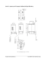
Страница 105: ...nical Specifications Mechanical Specifications The following sections show 3D views and the mechanical dimensions for Genie with C mount or CS mount and also for Genie with right angled lens mounts Additional notes follow the figures Genie 3D View with C mount and CS mount ...

Страница 106: ...104 Technical Specifications Genie HM HC Series GigE Vision Camera Genie C mount and CS mount Mechanical Specifications Note Overall length tolerance is 0 35mm ...

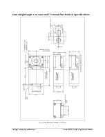
Страница 107: ...Genie HM HC Series GigE Vision Camera Technical Specifications 105 Genie 3D View with Right angle C mount and CS mount ...

Страница 108: ...106 Technical Specifications Genie HM HC Series GigE Vision Camera Genie Right angle C mount and CS mount Mechanical Specifications Note Overall length tolerance is 0 35mm ...

Страница 109: ...verall length tolerance is 0 35mm Overall height or width tolerance is 0 15mm Sensor Alignment Specification The following figure specifies sensor alignment for Genie where all specifications define the absolute maximum tolerance allowed for production cameras Dimensions x y z are in microns and referenced to the Genie mechanical body or the optical focal plane for the z axis dimension Theta speci...

Страница 110: ...enie camera 12 pin male Hirose connector The table below the figure lists the Genie I O signal specifications Pin Direction Genie Signal see details below Notes 1 Power GND 2 12V DC power supply 11 to 25 2 Volts DC at 0 6 Amp minimum 11 to 15 2 Volts DC at 0 6 Amp minimum see also Camera Performance Specifications xx GM00 xxxxx models xx GEN0 xxxxx models 3 Out Output 1 4 Out Output 1 5 In Input 1...

Страница 111: ...al external current limiting see figure below Used as trigger or integration control External signal polarity selected via configuration parameter User programmable debounce time from 1 to 255µs See Input Controls via Sapera LT or GigE Vision Compliant Applications on page 55 The opto coupler is typically a Fairchild HMHA281 with the following characteristics Input Electrical Parameter Description...

Страница 112: ...ose 12 connector V Event Signal Buffer driver example 74HC244 Trigger Debounce IN 3 3V Genie RS 422 External Signal Example 4 7K Fairchild HMHA281R 01µf 680 IN IN Hirose 12 connector Event Signal Buffer driver example SN75179B Trigger Debounce IN 3 3V Genie 24 Volt External Signal Example 4 7K Fairchild HMHA281R 01µf 680 IN IN Hirose 12 connector 680 1 2W Event Signal ...

Страница 113: ...40 µs RJ45 LAN Ethernet Connector Details The RJ45 LAN connector has two LEDs for network status conditions The LED color codes are as follows Network Connection Network Activity Green 100Mbps Off no network activity Orange 1000Mbps Yellow typically blinking active Network Connection Network Activity The Genie LAN connector is a standard Ethernet socket Use CAT5e or CAT6 certified Ethernet cables ...

Страница 114: ...nents contribute to the successful design of an imaging solution Illumination The amount and wavelengths of light required to capture useful images depend on the particular application Factors include the nature speed and spectral characteristics of objects being imaged exposure times light source characteristics environmental and acquisition system specifics and more The DALSA Web site http mv da...

Страница 115: ...ens should be available from the lens data sheet or from the lens manufacturer Primed quantities denote characteristics of the image side of the lens That is h is the object height and h is the image height The focal point is the point at which the image of an infinitely distant object is brought to focus The effective focal length f is the distance from the second principal point to the second fo...

Страница 116: ...y brief information on other lens parameters to consider Lens Mount As shown in Mechanical Specifications on page 103 Genie comes in C mount and the CS mount The CS mount is a standard with a shorter flange focal length for space sensitive applications The C mount Back Focal Distance is 17 52 mm while CS mount Back Focal Distance is 12 52 mm The lens selected must be for the Genie mount used else ...

Страница 117: ...nsor of 10 40mm by 7 60mm a diagonal of 12 88mm The outer circle shows the illumination coverage of a 1 inch lens where a sensor of up to 16mm diagonal is evenly exposed The inner circle shows the illumination coverage of a 2 3 inch lens where a sensor of up to 11mm diagonal is evenly exposed The obvious conclusion is that a 2 3 inch lens will produce image vignetting at the sensor edges while a 1...

Страница 118: ...verage Lens Sensor Size vs Genie HM model Each Genie HM sensor has a square pixel of 7 4 x 7 4 µm The following table lists the lens size required for total illumination and the next smaller lens size which will have some vignetting Genie Model Illumination Coverage Genie HM 1400 Genie HM 1024 Genie HM 640 Complete Illumination 1 inch Lens 2 3 inch Lens 1 3 inch Lens Some Vignetting 2 3 inch Lens ...

Страница 119: ...lens with poor resolution seems to never be in focus when used to image fine details Aberrations defect chromatic spherical Aberrations are specific types of lens faults affecting resolution and distortion Lens surface defects or glass faults distort all light or specific colors Aberrations are typically more visible when imaging fine details Spatial Distortions Describes non linear lens distortio...

Страница 120: ...will normally have brighter pixels adjacent to darker pixels The location of these pixels changes with the angle of illumination Cleaning the Sensor Window Even with careful handling the sensor window may need cleaning The following steps describe various cleaning techniques to clean minor dust particles to accidental finger touches Use compressed air to blow off loose particles This step alone is...

Страница 121: ...ie is installed in a high vibration environment All Genie versions support this secure Ethernet cable All cables made in U S A all cables RoHS compliant CAT6 certified tested for near end far end crosstalk and return loss IGE 3M 3meters IGE 10M 10meters IGE 25M 25meters IGE 50M 50meters IGE 100M 100meters For Information contact Components Express Inc CEI 10330 Argonne Woods Drive Suite 100 Woodri...

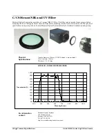
Страница 122: ...ecifications and pass spectrum Contact Midwest Optical Systems directly for technical information and pricing Physical Specifications Outside diameter 25 4mm 32 NS2A thread c mount thread Clear Aperture 19 5mm Thickness 3 0 0 1mm BP550 UV NIR BLOCK VISIBLE PASS 0 00 10 00 20 00 30 00 40 00 50 00 60 00 70 00 80 00 90 00 100 00 350 450 550 650 750 850 950 1050 Wavelength nm Transmission For Informat...

Страница 123: ... sensor surface see text C Mount Filter Illustration Change of Focal Point with inserted C mount filter In this example using the Midwest Optical Systems C mount NIR UV filter the image will be projected about 1 3 of the filter thickness behind the sensor plane In order to compensate for this the fixed focus C mount lens needs to be unscrewed counterclockwise 1 3 of filter thickness or 1000 micron...

Страница 124: ...me rate possible refer to the DALSA Network Imaging Package user s manual Ethernet Switch Requirements When there is more than one device on the same network or a camera to PC separation greater than 100 meters an Ethernet switch is required Since the Genie GigE camera complies with the Internet Protocol it should work with all standard Ethernet switches However switches offer a range of functions...

Страница 125: ...int GX from Omnitron Systems www omnitron systems com converts GigE to fiber transmission and vice versa It supports multimode MM fiber over distances of up to 220 m 720 ft and single mode SM fiber up to 65 km 40 mi with SC MT RJ or LC connector types Important The inclusion in this manual of GigE to fiber optic converters does not guarantee they will meet specific application requirements or perf...

Страница 126: ...124 Technical Specifications Genie HM HC Series GigE Vision Camera EC FCC Declaration of Conformity ...

Страница 127: ... there is some type of IP error The GigE server tray icon when the Genie device is found The Genie has obtained an IP address and there are no network issues Optimization may still be required to maximize performance Problem Type Summary Genie problems are either installation types where the Genie is not found on the network or setup errors where the Genie device is found but not controllable Addi...

Страница 128: ...enie package again Device Available but with Operational Issues A properly installed Genie with no network issues may still not perform optimally Operational issues concerning cabling Ethernet switches multiple cameras and camera exposure are discussed in the following sections Always Important Why should Genie firmware be updated See Firmware Updates on page 128 Power Failure During a Firmware Up...

Страница 129: ...acquire a DHCP address Registry writes fail Messages in the Sapera Log Viewer include check your firewall and the computer firewall is disabled for no reason After installing Windows XP Service Pack 2 or 3 the Windows Firewall service will not start Symptoms may include the following messages When you click Windows Firewall in Control Panel you may receive the following error message Windows Firew...

Страница 130: ...th the older vision application New Genie cameras must not be programmed with older firmware Power Failure During a Firmware Update Now What Don t panic There is far greater chance that the host computer OS is damaged during a power failure than any permanent problems with the Genie When electrical power returns and the host computer system has started follow this procedure to reprogram the Genie ...

Страница 131: ...re should not be any packet resend messages else this indicates a control or video transmission problem due to poor connections or extremely high EMI environments Acquisition Error without Timeout Messages Streaming video problems range from total loss of image data to occasional loss of random video data packets The following section describes conditions identified by DALSA engineering while work...

Страница 132: ...is typically done for any camera installation to quickly verify the Genie and its software package See Internal Image Test Patterns on page 70 for information on using CamExpert to select internal patterns from Genie Other Problems or Issues This section describes problems that do not fit any of the categories above Typically these are issues found in the field under specific or unusual conditions...

Страница 133: ...bert Joncas Suite 142 St Laurent Quebec Canada H4M 2Z2 Tel 514 333 1301 Fax 514 333 1388 DALSA Billerica office 700 Technology Park Drive Billerica Ma 01821 Tel 978 670 2000 Fax 978 670 2010 Asia Sales European Sales DALSA Asia Pacific Ikebukuro East 13F 3 4 3 Higashi Ikebukuro Toshima ku Tokyo Japan Tel 81 3 5960 6353 Fax 81 3 5960 6354 DALSA Europe Breslauer Str 34 D 82194 Gröbenzell Munich Germ...

Страница 134: ...sa com mv download Before contacting Technical support the following three status files should be generated and included with the request for support The host computer network status file refer to the DALSA Network Imaging Package user s manual for information on generating this file From the computer folder installation drive DALSA Genie bin there is a report txt file automatically generated on f...

Страница 135: ...ing consecutive addresses DHCP Dynamic Host Configuration Protocol Protocol which provides a mechanism for allocating IP addresses dynamically by a DHCP server on a network Typically dedicated DHCP servers are a component of corporate networks Used for managed networks Driver Also called a device driver a program routine that links a peripheral device to the operating system a device driver is req...

Страница 136: ...otocol is the method by which data is sent from one computer to another on a network or across the Internet Each device must have an IP address to identify that device on the network or on the Internet LLA Link Local Address is a protocol providing a scheme for devices to automatically assign themselves an IP address and check for IP conflict Used in unmanaged networks NIC Network Interface Card C...

Страница 137: ...anism that initiates an action when an event occurs such as synchronizing an image acquisition to an external event A trigger generally causes a program routine to be executed such as the resetting of camera exposure and or the firing of a strobe light UDP User Datagram Protocol is a connectionless transport protocol providing no guaranty of delivery or reliability GigE Vision Control Protocol and...

Страница 138: ...136 Glossary of Terms Genie HM HC Series GigE Vision Camera ...
Страница 139: ...nts 71 exposure duration 47 exposure period 129 Exposure time granularity 51 external trigger 129 F fast frame rate 40 fastest frame rates 47 feature availability 85 feature interdependence 85 feature type 76 fiber optic light sources 112 firewall exceptions 20 firmware update 21 28 Flat Field calibration preparations 64 flat field correction 63 flow control protocol 122 focal point 113 frame rate...

Страница 140: ...ight sensitivity 45 LUT examples 100 LUT table 61 M MAC address 30 managed network 94 maximum frame rate 51 N network configuration 27 Network Configuration Mode 74 Network Configurations 19 Network Imaging driver 23 network optimizations 73 network status 24 111 NIR UV filter 120 O object distance 113 operational status 25 112 optimize network 73 opto coupled inputs 54 opto coupled outputs 56 opt...

Страница 141: ...oftware triggers 46 spatial resolution 45 Static electricity 19 static IP address 95 status LED sequence 25 strobe light 56 subnet 23 synchronization timing 47 synchronous exposure 51 T test pattern generator 70 test patterns 29 third party filter driver 126 threshold processes 61 Transfer events 71 U unmanaged networks 93 User Name 30 user defined name 30 V vertical and horizontal cropping 42 ver...

Отзывы: