background image


               5

HDD Mounting


► 

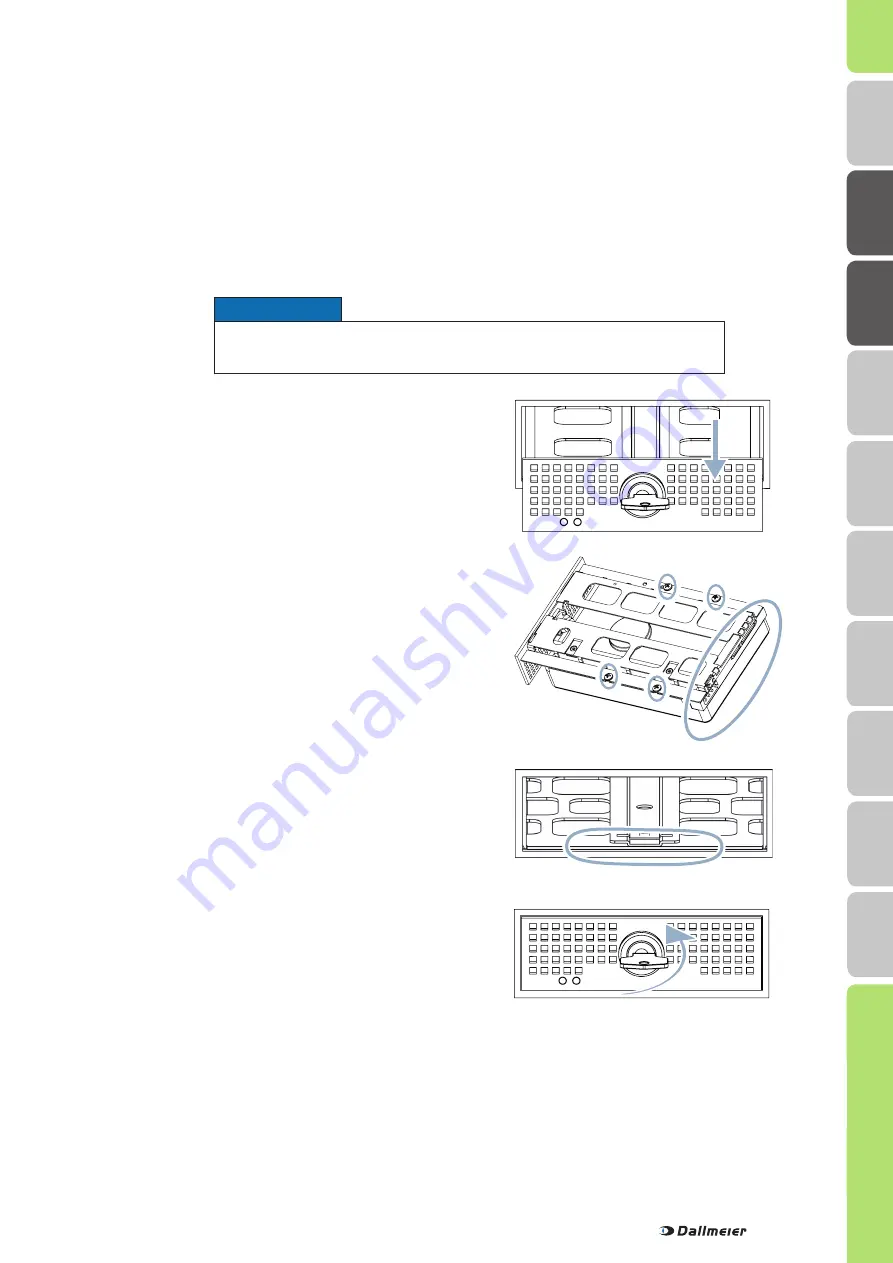
Ensure that HDD drawer unit and housing are flush.


  Lock the HDD drawer unit with the key.

The HDD will be initialised and set into operation during the first 
start of the device.


► 

Place the HDD drawer unit on the HDD’s underside.


► 

Ensure that the connections of the HDD are positioned     


at the rear side of the HDD drawer unit.


  Ensure that HDD and HDD drawer unit flush at the rear     

  side.


► 

Mount the HDD drawer unit on the HDD with 4 screws.


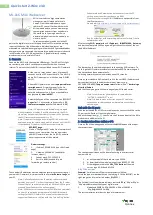
  Unlock the HDD drawer unit with the key.


► 

Pull the HDD drawer unit carefully out of the housing.


► 

Remove the cover panel mounted on the HDD drawer unit.


► 

Insert the HDD drawer unit into the guide rail.


► 

Slide the HDD drawer unit carefully and completely into    

  the 

housing.


► 

Ensure that you slide it straight.


  Do not use any force.

Devices that have been ordered with hard disk drives can be mounted, connected and commissioned directly.  
Devices that have been ordered without hard disk drives must be equipped with one 3.5" hard disk drive at least.

Note that all mounted hard disk drives

  must be tested and released for mounting by Dallmeier (HDD whitelist in the Partner Forum)!

  may not be formatted or partitioned!

Also note that the HDD slots 1 (front side, top) must be used in case only one hard disk drive is mounted:

Depending on the number and properties (capacity, new or used) of the mounted hard disk drives, various messages and 
dialogues are displayed during the first start and the initialization.


► 

Confirm the messages, if required.


► 

Observe the instructions given in the dialogues.


► 

Note the appropriate Configuration documentation.


► 

Load the Default System Parameters as first step of the configuration.

IMPORTANT ADVICE

Notice

Ensure that the device is switched off and disconnected from  
the power supply.

H

DD Moun

ting

Moun

ting

Saf
ety

Requir

emen

ts

DL

S 1600

Local L

ogin

Dimensions

D

M

S 2400

Remote L

ogin

Indica

tors

Содержание DMS 2400

Страница 1: ...PRELOADED English Commissioning 003864 Rev 1 0 5 2014 03 13 Appliance DMS 2400 DLS 1600...

Страница 2: ...dicates a hazardous situation which if not avoided will result in death or serious injury Warning WARNING indicates a hazardous situation which if not avoided could result in death or serious injury C...

Страница 3: ...protection against overvoltages and the immunity of information and communication technology equipment to electromagnetic interferences EMI all protec tive measures which are specified by the current...

Страница 4: ...otection of Electronic Computer Data Processing Equipment ANSI NFPA 75 Secured room Risk of manipulation and sabotage A stand alone installation should be operated in secured rooms with restricted acc...

Страница 5: ...be mounted connected and commissioned directly Devices that have been ordered without hard disk drives must be equipped with one 3 5 hard disk drive at least Note that all mounted hard disk drives mu...

Страница 6: ...he device into the 19 rack Observe the instructions of the rack manufacturer Ensure 4 10cm of free space at the front rear and right side Connect the device as described on the following pages Commiss...

Страница 7: ...7 Dimensions 445mm 133mm 425mm 133mm 95mm 38mm 427mm 431mm 424mm HDD Mounting Mounting Safety Requirements DLS 1600 Local Login Dimensions DMS 2400 Remote Login Indicators...

Страница 8: ...3 5mm Phone Jack 3 not active C Contact IN global 1 6 Weidm ller 8 pins only for switch push button dry contact O Microphone IN 3 5mm phone jack red 4 3kOhm 2 828Vpp D Mouse PS 2 green P Audio OUT 3 5...

Страница 9: ...2 pol Pin Assignment 1 12V DC 2 GND Pin Assignment 7 Contact 6 8 GND Pin Assignment 1 GND 2 Contact 1 3 Contact 2 Pin Assignment 4 Contact 3 5 Contact 4 6 Contact 5 Pin Assignment 7 Contact 6 8 GND Pi...

Страница 10: ...ptional L Microphone IN 3 5mm phone jack red 4 3kOhm 2 828Vpp C Contact IN global 1 6 Weidm ller 8 pins only for switch push button dry contact M Video OUT 1 2 BNC 75Ohm 1Vpp CVBS video only no config...

Страница 11: ...Audio 1 2 Audio 2 3 Audio 3 4 Audio 4 5 Audio 5 Pin Assignment 6 Audio 6 7 Audio 7 8 Audio 8 9 GND 1 10 GND 2 Pin Assignment 11 GND 3 12 GND 4 13 GND 5 14 GND 6 15 GND 7 8 Audio IN Q D SUB 15 pol with...

Страница 12: ...te In the initial state cameras are displayed with wildcards on the user interface Login In the initial state it is possible to login without a password The rights of the Administrator group are valid...

Страница 13: ...information is displayed The password input field is displayed Login In the initial state it is possible to login remote using the serial number as password The rights of the Administrator group are v...

Страница 14: ...ra failures or hard disk faults F USB interface USB 2 0 type A G HDD DVD RW drives Behind the flap H Display Shows information and status messages Indicators Information and status messages are output...

Страница 15: ...15 Notes HDD Mounting Mounting Safety Requirements DLS 1600 Local Login Dimensions DMS 2400 Remote Login Indicators...

Страница 16: ...the grant of a patent utility model or design We reserve the right to make technical modifications The manufacturer accepts no liability for damage to property or pecuniary damages arising due to mino...

Отзывы: