DALEMANS DAT 420 Скачать руководство пользователя страница 14


www.dalemans.com


DAT420_MAN02_EN.docx • V1R1 


10 


DAT 420 

6.3 

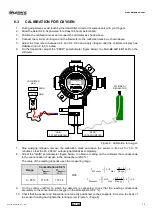
CALIBRATION FOR OXYGEN 

1. 

During adjustment, avoid touching the transmitter circuit or its components with your fingers. 

2. 

Allow the detector to be powered for at least 24 hours beforehand. 

3. 

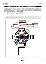
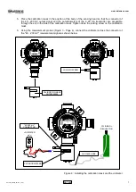
Position the calibration mask and connect the voltmeter as shown above. 

4. 

Connect the cylinder of nitrogen and the flowmeter to the calibration mask, as shown above. 

5. 

Adjust the flow rate to  between 0.4 and 0.6 l/min and apply  nitrogen until the voltmeter display has 
stabilised (min. 2 to 3 minutes). 

6. 

On the transmitter, adjust the "ZERO" potentiometer (figure below) to obtain 

40 mV ± 0.1 mV

 on the 

voltmeter. 


Figure 8 : Calibration for oxygen 

7. 

Stop  applying  nitrogen, remove the calibration mask  and leave the sensor  in free air for 5 to 10 
minutes so that the 40..200 mV output signal stabilises completely. 

8. 

Adjust the "GAIN" potentiometer (figure below) to obtain a reading on the voltmeter that corresponds 
to the concentration of oxygen in the atmosphere (20.9 %). 

The value of the reading depends upon the measuring range : 

Range


Concentration 20.9 %


With : 

4

4

20

+

×

=

Range

Gas

CAL

Measure

I


I

Measure 

mA


V

Measure 

mV


0 - 25 % 

17.376 

173.76 

10

4

4

20

×

+





×

=

Range

Gas

CAL

Measure

V


9. 

On the control  unit/PLC to which the detector is connected, check that the reading corresponds 
accurately to the concentration of oxygen in the atmosphere (20.9 %). 

10.  Check that the sensor and transmitter are correctly positioned on their supports. Screw on the body of 

the sensor housing and tighten the locking screw (Figure 5 - Page 6). 


CY 

REGULATOR 

VOLTMETER 

mV 




.






.




ZERO 

GAIN 

"GAIN" 

POTENTIOMETER 


"ZERO" 

POTENTIOMETER 


Содержание DAT 420

Страница 1: ...TOXIC GAS AND OXYGEN DETECTOR DAT 420 CALIBRATION MANUAL...

Страница 2: ...ntenance attempts carried out without observing the procedures described in this manual or without the assistance of our after sales service may prevent the equipment from working properly and consequ...

Страница 3: ...DAT420_MAN02_EN docx V1R1 ii DAT 420 Document DAT420_MAN02_EN DOCX Version V1R1 Date 11 07 2011...

Страница 4: ...1 7 TROUBLESHOOTING 12 8 ACCESSORIES AND SPARE PARTS 12 ILLUSTRATIONS AND TABLES Figure 1 Exploded view of the detector 3 Figure 2 Calibration mask 4 Figure 3 Measurement probes 4 Figure 4 Power suppl...

Страница 5: ...invalidate the essential safety requirements of the whole plant No additional drilling is allowed on the junction box The existing openings cannot be enlarged No additional terminal can be installed o...

Страница 6: ...time T90 45 sec Expected operating life span 2 years Supply voltage 15 30 Vdc Supply current Max 30 mA Storage temperature 40 C to 80 C Operating conditions Temperature range Ambient humidity Intermi...

Страница 7: ...emans Figure 1 Exploded view of the detector FLAMEPROOF d STOPPER PLUG SINTERED METAL FILTER SENSING HEAD BASE FPH01 STAINLESS STEEL FLAMEPROOF d JUNCTION BOX PRE00000033 BOI00000188 MEC00000010 VISVI...

Страница 8: ...or PVC with approximately 4 mm interior diameter TUB00000009 A measurement probes set fitted with a connector with a pitch of 2 mm ACC00000012 see figure below A digital voltmeter A precision insulat...

Страница 9: ...e to use the OctoPRO calibration unit to simulate the 4 20 mA current loop Contact Dalemans for further information The 4 20 mA current loop may also be simulated as follows 1 Power the detector from...

Страница 10: ...ation consists of creating a calibration atmosphere around the sensing head by injecting a reference gas To avoid contamination of the calibration gas by the ambient atmosphere or air draughts always...

Страница 11: ...essible through the slot in the side of the calibration mask Tighten down the locking screw on the calibration mask 6 Using the measurement probes Figure 3 Page 4 connect the voltmeter across the conn...

Страница 12: ...to 3 minutes 5 On the transmitter adjust the ZERO potentiometer figure below to obtain 40 mV 0 1 mV on the voltmeter Figure 7 Calibration for toxic gases 6 Stop applying nitrogen and wait until the 40...

Страница 13: ...300 20 00 200 00 13 60 136 00 8 80 88 00 4 96 49 60 500 20 00 200 00 12 00 120 00 5 60 56 00 1000 20 00 200 00 7 20 72 00 2000 10 40 104 00 9 On the control unit PLC to which the detector is connecte...

Страница 14: ...n remove the calibration mask and leave the sensor in free air for 5 to 10 minutes so that the 40 200 mV output signal stabilises completely 8 Adjust the GAIN potentiometer figure below to obtain a re...

Страница 15: ...tor 0 500 4 Diborane B2H6 0 300 2 Fluorine F2 Calibration with Cl2 generator Hydrazine N2H4 Gaseous permeation 5 Hydrochloric acid HCl 0 300 3 Hydrocyanic acid HCN 0 250 1 Hydrofluoric acid HF 0 500 5...

Страница 16: ...OUT00000089 Hose PVC 4 mm TUB00000009 Key for locking screw 1 5 mm hex key OUT00000115 Measurement probes Pitch 2 mm ACC00000012 Spanner for the base of the sensing head 30 mm OUT00000114 Spanner for...

Страница 17: ...DALEMANS s a Rue Jules M lotte 27 B 4350 Remicourt Tel 32 0 19 54 52 36 Fax 32 0 19 54 55 34 info dalemans com www dalemans com...

Отзывы: